Leuze electronic GmbH + Co. KG
In der Braike 1 D-73277 Owen
We reserve the right to make changes
[email protected] • www.leuze.com
Tel. +49 (0) 7021 573-0
03/2020 - 50134631-02 - 6/20
4
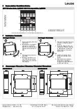
Function chart
A1/A2/LED power supply
Two-hand pushbutton T1
Two-hand pushbutton T2
Synchronous monitoring
11 - 14 enable branch, LED.K1
11 - 12 signalling branch
t
A
= response time
t
R
= release time
t
W
= recovery time
t
S
= synchronous monitoring time
(1) Enable for synchronous operation
(2) No re-enable if operation is interrupted
(3) No enable as recovery time t
W
is too short
(4) No enable as synchronous monitoring time t
S
is too long
5
Technical data
Function
Two-hand monitoring relay
Function indicator
2 LEDs, green
Version
24 V AC/DC
Power circuit
Rated voltage U
N
A1, A2
24 V AC/DC
Operating voltage range U
B
: 0.85 - 1.1 × U
N
20.4 to 26.4 V AC/DC
Rated power (max)
2 VA / 1 W
(2.3 VA / 1.3 W)
Rated frequency
50-60 Hz
Residual ripple
2.4 V
SS
Electrical isolation between supply and control circuits
No
Control circuits
T11
T12
T13
Rated output voltage
24 V DC
Input current
2.5 mA
25 mA
Max. peak current
3 mA
60 mA
Response time t
A
< 20 ms
Recovery time t
W
> 250 ms
Release time t
R
< 20 ms
Synchronous time monitoring t
S
≤
500 ms
Max. line resistance per channel
(5 + (1.176 × U
B
/ U
N
- 1) × 100)
Ω
Output circuits
Enabling current path 11-14
Signalling current path 11-12
Switching function
Changeover contact
(NO contact)
Changeover contact
(NC contact)
Conditional short-circuit current
350 A
300 A
Contact material
Ag alloy
Rated switching voltage
230 V AC
Max. thermal permanent current I
TH
5 A
Utilisation category
AC-15: U
e
230 V, I
e
3 A
DC-13: U
e
24 V, I
e
2 A
Short circuit protection
4 A class gG fuse, fuse integral
< 1
00 A²s
Mechanical service life
10
7
switching cycles
General data
Air gap and creepage paths between the circuits
EN 60664-1 (pollution degree 2)
Protection class according to EN 60529
IP40/IP20 (case/terminals)
Ambient operating temperature
- 25 to +55 ℃
Storage temperature
- 25 to +75 ℃
Weight
100 g
Standards
EN ISO 13849-1, EN 62061, ISO 13851:2019
Terminal and connection data
Screw terminals
(1 clamping point per contact)
Spring-loaded terminals
(2 clamping points per contact)
Single-core or finely stranded
1× 0.2 - 2.5 mm²
2× 0.2 - 1.0 mm²
2× 0.2-1.5 mm²
Finely stranded with wire-end ferrule
1× 0.25 - 2.5 mm²
2× 0.25 - 1.0 mm²
2× 0.25 - 1.5 mm²
AWG conductor size (only use Cu wires)
26 - 14
24 - 16
Maximum tightening torque
0.5 - 0.6 Nm (5 - 7 lbf-in)
Stripping length
7 mm
7 mm


