Appendix
11-44
BA9300SU EN 2.1
Code
Important
Possible settings
LCD
Code
Important
Choice
Lenze
LCD
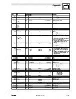
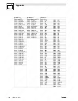
[C0890]
1RFS
5050
→
Selection list 1
NSET-NOUT
Speed setpoint input
[C0891]
0D''
1000
FIXED0%
→
Selection list 1
Configuration torque setpoint input
[C0892]
MO0MJN
5700
ANEG1-OUT
→
Selection list 1
Configuration lower torque limit
[C0893]
IJ0MJN
19523
FCODE-472/3
→
Selection list 1
Configuration upper torque limit
[C0894]
PIJRFS
1000
FIXED0INC
→
Selection list 3
Configuration rotor position setpoint
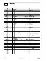
[C0895]
PIJMJN
1006
FIXED100%
→
Selection list 1
Configuration phase controller limit
[C0896]
1MJN
1000
FIXED0%
→
Selection list 1
Configuration 2nd speed limit value
[C0897]
PIJO1
1000
FIXED0
→
Selection list 2
Configuration switch-on signal phase controller
[C0898]
GM'UFDL
1006
FIXED100%
→
Selection list 1
Signal for field weakening
[C0899]
1NRUS
1000
FIXED0
→
Selection list 2
Changeover between n and M control
[C0900]
QRP
10250
R/L/Q-QSP
→
Selection list 2
Control signal for release
[C0901]
JRFS
1000
FIXED0%
→
Selection list 1
Load I-component of the speed controller
[C0902]
JMOD'
1000
FIXED0
→
Selection list 2
Trigger signal for loading I component of speed
controller
[C0903]
3$'$37
1006
FIXED0%
→
Selection list 1
MCTRL-BOOST Adaptation phase controller
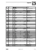
C0906
1
2
3
4
5
6
7
8
9
1RFS
ND''
MONMJN
IJNMJN
PIJMJN
1MJN
GM'UFDL
JRFS
3$'$37
g
-199.99
{0.01 %}
199.99
Analog input signals of MCTRL
C0907
1
2
3
4
PIJO1
10RUS
QRP
JMOD'
g
digital input signals
C0908
PIJRFS
g
-2147483647
{1 inc}
2147483647
Set phase signal
•
1 turn = 65536 inc
C0909
RPFF' MJNJS
1
1
{1}
2
Limitation of direction of rotation for the speed
setpoint
1
+ /- 175 %
2
0 .. + 175 %
3
-175 .. 0 %
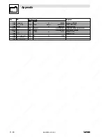
[C0920]
O1
1000
FIXED0
→
Selection list 2
Activation input homing
[C0921]
ND5L
1000
FIXED0
→
Selection list 2
Digital reference switch
[C0922]
PIJJ1
1000
FIXED0INC
→
Selection list 3
Phase input
[C0923]
1J1
1000
FIXED0%
→
Selection list 1
Speed input
[C0924]
326/2$'
1000
FIXED0
→
Selection list 2
Control ”set position”
[C0925]
$&7326,
1000
FIXED0INC
→
Selection list 3
Position ”set position”
C0926
1
2
3
4
&
&
$&7326
7$5*(7
g
-2147483647
{1 inc}
2147483647
Display of
1. C0925
2. C0922
3. Actual position
4. Target position
C0927
1
2
3
&
&
/2$'
g
Display of
1. C0920
2. C0921
3. C0924
C0928
&
g
-2147483647
{1 inc}
2147483647
Phase signal (contouring error) of REF
•
1 turn = 65536 inc
C0929
&
g
-199.99
{0.01 %}
199.99
Analog input signal
[C0930]
*FD5%OV NOS
1
1
{1}
65535
Gearbox factor (numerator)
[C0931]
*FD5%OV F1E
1
1
{1}
65535
Gearbox factor (denominator)
Summary of Contents for EVS9321-CS
Page 3: ...Operating Instructions EDB9300UES 00414796 Global Drive 9300 servo ...
Page 21: ...Technical data 3 8 BA9300SU EN 2 1 ...
Page 57: ...Installation 4 36 BA9300SU EN 2 1 ...
Page 73: ...During operation 6 4 BA9300SU EN 2 1 ...
Page 117: ...Troubleshooting and fault elimination 9 10 BA9300SU EN 2 1 ...
Page 119: ...Maintenance 10 2 BA9300SU EN 2 1 ...
Page 188: ...Appendix 11 69 BA9300SU EN 2 1 ...
Page 189: ...Appendix 11 70 BA9300SU EN 2 1 ...


