background image

Appendix

11-40

BA9300SU EN 2.1

Code

Important

Possible settings

LCD

Code

Important

Choice

Lenze

LCD

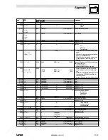
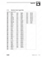
[C0786]

MOD'

5001

MCTRL-QSP-OUT

Selection list 2

Digital input (load ramp function generator)

[C0787]

1
2
3
4

KOH

KOH

KOH

KOH

53
1000
1000
1000

Selection list 2

DIGIN3
FIXED0
FIXED0
FIXED0

Configuration JOG selection and JOG activation
Binary interpretation

[C0788]

1
2
3
4

SJ

SJ

SJ

SJ

1000
1000
1000
1000

Selection list 2

FIXED0
FIXED0
FIXED0
FIXED0

Configuration Ti selection and Ti activation

Binary interpretation

Tir and Tif pairs are identical

[C0789]

5GH

1000

FIXED0

Selection list 2

Digital input (ramp function generator 0)

[C0790]

5GHRSOP

1000

FIXED0

Selection list 2

Digital input (ramp function generator stop)

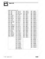
C0798

1
2

EJ1ITDM

RFS

g

-199.99

{0.01 %}

199.99

analog input signals

C0799

1
2
3
4
5
6
7
8
9

10
11
12
13

1J1T

1D''J1T

MOD'

KOH

KOH

KOH

KOH

SJ

SJ

SJ

SJ

'JR 5GH

5GHRSOP

g

Display digital input signals of NSET

[C0800]

RFS

1000

FIXED0%

Selection list 1

Configuration setpoint input

[C0801]

DES

1000

FIXED0%

Selection list 1

Configuration actual value input

[C0802]

J1GM8

1000

FIXED0%

Selection list 1

Configuration evaluation input

[C0803]

D'DPS

1000

FIXED0%

Selection list 1

Configuration adaptation input

[C0804]

J1DES

1000

FIXED0

Selection list 2

Configuration inactivation input

[C0805]

JOGG

1000

FIXED0

Selection list 2

Digital input (switch-off I component)

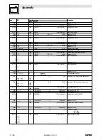
C0808

1
2
3
4

&

&

&

&

g

-199.99

{0.01 %}

199.99

Display of

&

&

&

&

C0809

1
2

&

&

g

Display of
C0804
C0805

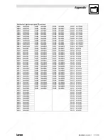
[C0810]

1
2

J1

J1

55
1000

Selection list 1

AIN2-OUT
FIXED0%

Analog inputs ASW1

[C0811]

RFS

1000

FIXED0

Selection list 2

Digital input ASW1

C0812

&

g

-199.99

{0.01 %}

199.99

Display of C0810

C0813

&

g

Display of C0811

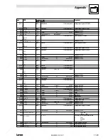
[C0815]

1
2

,1

,1

1000
1000

FIXED0%

Selection list 1

Analog input ASW2

[C0816]

6(7

1000

FIXED0

Selection list 2

Digital input ASW2

C0817

&

g

-199.99

{0.01%}

199.99

Display of C0815

C0818

&

g

Display of C0816

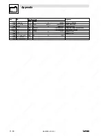
[C0820]

1
2
3

J1

J1

J1

1000

FIXED0

Selection list 2

Digital inputs AND1

Summary of Contents for EVS9321-CS

Page 1: ...ugosza 2 6 Street 51 162 Wrocław Poland biuro rgbelektronika pl 48 71 325 15 05 www rgbautomatyka pl www rgbelektronika pl DATASHEET www rgbautomatyka pl www rgbelektronika pl OTHER SYMBOLS EVS9323 ESV004 EVS9323ESV004 EVS9323 ESV004 EVS9323 ESV004 LENZE ...

Page 2: ...ed with a wide variety of tools and having several testing stands at their disposal are a guarantee of the highest quality service OUR SERVICES ENCODERS SERVO DRIVERS LINEAR ENCODERS SERVO AMPLIFIERS CNC MACHINES MOTORS POWER SUPPLIERS OPERATOR PANELS CNC CONTROLS INDUSTRIAL COMPUTERS PLC SYSTEMS Repair this product with RGB ELEKTRONIKA ORDER A DIAGNOSIS Buy this product at RGB AUTOMATYKA BUY ...

Page 3: ...Operating Instructions EDB9300UES 00414796 Global Drive 9300 servo ...

Page 4: ... and index Software level and index Variant Explanation 2000 Lenze GmbH Co KG No part of this documentation may be reproduced or made accessible to third parties without written consent by Lenze GmbH Co KG We have thoroughlycollectedall specificationsinthisdocumentationandhave checkeditforcompliance withthe describedhardware andsoftware Howe ver differences cannot be excluded completely We are not...

Page 5: ... t i o n U V W R D Y I M P I m a x M m a x F a i l 1 2 7 6 2 3 4 7 6 3 A 4 S T 2 5 9 S T 1 A 3 A 2 A 1 E 3 E 5 3 9 E 4 E 2 E 1 2 8 G N D L O H I M C T R L N A C T X 4 X 5 X 6 X 8 X 9 P E P T C U V W L 1 L 2 L 3 U G U G X 1 0 T 1 T 2 1 5 5 1 5 1 1 5 S c r e e n c o n n e c t i o n 1 2 5 0 r p m X 7 S c r e e n p l a t e m o t o r c a b l e s S c r e e n p l a t e c o n t r o l c o n n e c t i o n s...

Page 6: ... information 2 1 2 1 Safety and application notes for Lenze controllers 2 1 2 2 Layout of the safety information 2 2 2 3 Residual hazards 2 2 3 Technical data 3 1 3 1 Features 3 1 3 2 General data operating conditions 3 2 3 3 Rated data 3 3 3 3 1 Types 9321 to 9325 3 3 3 3 2 Types 9321 to 9324 with 200 overcurrent 3 4 3 3 3 Types 9326 to 9332 3 5 3 3 4 Fuses and cable cross sections 3 6 3 3 5 Main...

Page 7: ...nection of a brake unit 4 17 4 2 7 4 DC bus connection of several drives 4 18 4 2 8 Control connections 4 20 4 2 8 1 Control cables 4 20 4 2 8 2 Assignment of the control terminals 4 20 4 2 8 3 Connection diagrams 4 22 4 2 9 Motor temperature monitoring 4 28 4 2 9 1 User specific characteristic for a PTC thermistor 4 29 4 2 10 Feedback systems 4 30 4 3 Installation of a CE typical drive system 4 3...

Page 8: ...rameter set 7 12 7 2 5 Parameter set transfer 7 14 7 2 6 Password protection 7 16 7 3 Display functions 7 16 8 Configuration 8 1 8 1 Predefined configurations 8 1 8 1 1 Working with predefined configurations 8 1 8 2 Operating modes 8 2 8 2 1 Parameter setting 8 2 8 2 2 Control 8 2 8 2 3 Configuration with Global Drive Control 8 3 8 3 Working with function blocks 8 4 8 3 1 Signal types 8 4 8 3 2 El...

Page 9: ...1 11 Appendix 11 1 11 1 Accessories 11 1 11 2 Application examples 11 2 11 2 1 Speed control 11 2 11 2 2 Torque control with speed limitation 11 5 11 2 3 Digital frequency master drive 11 7 11 2 4 Digital frequency bus slave drive 11 10 11 2 5 Digital frequency cascade slave drive 11 12 11 3 Code table 11 15 11 4 Selection lists of signal links 11 51 11 5 Motor selection list 11 56 11 5 1 Servo mo...

Page 10: ...her Lenze drive components 1 1 2 What is new what has changed Material no Edition Important Contents 391489 01 1997 1st edition 395638 05 1997 substitues 391489 Chapter 3 3 Chapter 4 1 2 Chapter 6 2 2 403496 06 1998 substitues 395638 Chapter 1 4 revised Acceleration drive mode Oscilloscope function 414796 05 2000 substitues 403469 Chapter 3 3 5 Mains filter Chapter 4 2 4 Mains types mains conditio...

Page 11: ... public mains for operation in industrial premises and residential areas The user is responsible for the compliance of his application with the EC directives Any other use shall be deemed as inappropriate Liability The information data and notes in these instructions met the state of the art at the time of printing Claims on modifications referring to controllers which have already been supplied c...

Page 12: ...priate handling must be observed The climatic conditions according to EN 50178 VDE 0160 must be observed 4 Installation The units must be installed and cooled according to the regulations given in the corresponding documentation The controllers must be protected from inappropriate loads Particularly during transport and handling components must not be bent and or insulation distances must not be c...

Page 13: ...This note designates general useful notes If you observe it handling of the controller drive system is made easier 2 3 Residual hazards Protection of persons After mains voltage disconnection the power terminals U V Wand UG UG carry hazardous voltages at least 3 minutes after mains disconnection Before working on the controller check that no voltage is applied to the power terminals Protection of ...

Page 14: ...an be plugged Integrated phase controller for driftfree standstill Field oriented control for asynchronous and synchronous motors Vector modulation Digital synchronization system via digital frequency setpoint transmission without offset und gain errors Synchronization in speed and rotor position Homing function Application configuration for control functions and input output signals comprehensive...

Page 15: ... 2 EN 50082 1 EN 61800 3 Limit value class A to EN 55011 industrial area with mains filter A Limit value class B acc to EN 55022 residential area with mains filter B and installation in control cabinet Noise immunity Limit values maintained using mains filter Requirements to EN 50082 2 EN 61800 3 Requirements Standard Severity Running time EN61000 4 2 3 i e 8 kV at air discharge and 6 kV at contac...

Page 16: ... 4 4 7 8 14 6 Max standstill current 8 kHz I08 A 2 3 3 8 5 9 10 5 19 5 Max standstill current 16 kHz I016 A 1 7 2 7 4 4 7 8 14 6 Ratings for operation at a mains 3 AC 480V 50Hz 60Hz Motor power 4 pole ASM Pr kW 0 37 0 75 1 5 3 0 5 5 p p Pr hp 0 5 1 0 2 0 4 0 7 5 Output power U V W 8kHz Sr8 kVA 1 2 2 1 3 2 5 8 10 8 Output power UDC UDC 2 PDC kW 2 0 0 75 2 2 0 75 0 Output current 8 kHz Ir8 A 1 5 2 5...

Page 17: ... Output current 16 kHz 2 Ir16 A 1 1 1 8 2 9 5 2 max output current 8 kHz 1 Imax8 A 3 0 5 0 7 8 14 0 max output current 16 kHz 1 Imax16 A 2 2 3 6 5 8 10 4 max standstill current 8 kHz I08 A 3 0 5 0 7 8 14 0 max standstill current 16 kHz I016 A 2 2 3 6 5 8 10 4 1 The currents apply to a periodical load cycle with 10 seconds overcurrent with the current mentioned here and 50 seconds base load with 44...

Page 18: ...2 0 80 0 110 0 126 0 Max standstill current 16 kHz I016 A 15 3 20 8 30 6 33 0 45 0 70 0 72 0 Ratings for operation at a mains 3 AC 480V 50Hz 60Hz Motor power 4 pole ASM Pr kW 11 0 18 5 30 0 37 0 45 0 55 0 90 0 p p Pr hp 15 0 25 0 40 0 49 5 60 0 73 5 120 0 Output power UVW 8 kHz Sr8 kVA 18 5 25 0 37 0 46 6 69 8 87 3 104 0 Output power UDC UDC 2 PDC kW 0 12 4 8 0 6 0 6 Output current 8 kHz Ir8 A 22 ...

Page 19: ...A 6 9 40A 6 9 9327 M 63A 63A 16 6 35A 35A 10 7 50A 10 7 9328 50A 50A 16 5 80A 16 5 9329 80A 80A 25 3 100A 25 3 9330 100A 100A 50 0 2 80A 1 2 16 2 5 9331 125A 125 A 70 2 0 2 100A 1 2 25 2 3 9332 160A 175 A 95 3 0 3 80A 1 3 16 3 5 1 The DC bus fuses are connected in parallel 2 The valid local regulations must be observed For operation of the controllers in a UL approved plant Use only UL approved fu...

Page 20: ...25 13 A 3 mH EZN3A0300H013 EZN3B0300H013 9326 24 A 1 5 mH EZN3A0150H024 EZN3B0150H024 9327 30 A 1 1 mH EZN3A0110H030 EZN3B0110H030 9328 42 A 0 8 mH EZN3A0080H042 EZN3B0080H042 9329 60 A 0 54 mH EZN3A0055H060 EZN3B0055H060 9330 90 A 0 37 mH EZN3A0037H090 EZN3B0037H090 9331 150 A 0 22 mH EZN3A0022H150 EZN3B0022H150 9332 150 A 0 22 mH EZN3A0022H150 EZN3B0022H150 The mains filters for RFI degree B con...

Page 21: ...Technical data 3 8 BA9300SU EN 2 1 ...

Page 22: ... to each other without free space in a control cabinet Ensure unimpeded ventilation of cooling air and outlet of exhaust air Allow a free space of 100 mm at the top and at the bottom Do not exceed the ambient temperature permissible during operation 3 2 With continuous oscillations or vibrations Check whether shock absorbers are necessary Possible mounting positions Vertically on the control cabin...

Page 23: ... 9330 C 340 672 591 28 5 283 624 38 285 265 11 28 18 9331 9332 C 450 748 5 680 30 5 389 702 38 285 265 11 28 18 When using a plug on fieldbus module Observe the free space required for the connection cables All dimensions in mm Controllers 9321 to 9326 Assembly preparation Take out fixing rail s accessory kit in the box and mount them on the controller housing Controllers 9327 to 9332 Remove cover...

Page 24: ...ordered from Lenze Distribution of the power loss approx 65 via the separated heat sink heat sink blower approx 35 inside the controller The type of protection of the separated cooler heat sink and blower is IP41 The ratings of the controller are still applicable Preparation for assembly 1 Lay the halves of the assembly frame into the slot provided on the controller 2 Push the frame halves togethe...

Page 25: ...1 e f g 9321 9322 112 5 385 5 350 60 95 5 365 5 105 5 250 92 6 5 9323 9324 131 5 385 5 350 79 114 5 365 5 105 5 250 92 6 5 9325 9226 135 385 5 350 117 137 5 365 5 105 5 250 92 6 5 Assembly cut out Type Height Width 9321 9322 82 3 9323 9324 350 3 101 3 9325 9326 350 3 139 3 When using an attachable fieldbus module Observe the free space required for the connection cables All dimensions in mm ...

Page 26: ... assembly with thermally separated power stage Type a b c1 c2 c3 d1 d2 d3 d4 e f g h 9327 9328 9329 280 379 28 140 252 41 141 238 338 250 90 6 9 Cut out Z Type Height Width k l m n 9327 9328 9329 338 1 238 1 20 2 259 2 20 2 359 2 When using an attachable fieldbus module Observe the free space required for the connection cables All dimensions in mm ...

Page 27: ...ensions for types 9321 Cx bis 9326 Cx a b d g Lenze b1 c e c a b d g Lenze b1 c2 a b d g Lenze b1 c K35 0059 Fig 4 4 Dimensions for assembly in Cold Plate technique Type a b b1 c c2 d e g 9321 Cx 9322 Cx 78 381 350 48 367 168 6 5 9323 Cx 9324 Cx 97 381 350 67 367 168 6 5 9325 Cx 9326 Cx 135 381 350 105 38 367 168 6 5 When using an attachable fieldbus module Observe the free space required for the ...

Page 28: ...x K35 0056 C A L Fig 4 5 Dimensions for assembly in Cold Plate technique Type a a1 b b1 c c1 c2 d e g 9327 Cx 9328 Cx 234 250 381 350 110 220 117 367 171 6 5 When using an attachable fieldbus module Observe the free space required for the connection cables All dimensions in mm ...

Page 29: ...ed the thermal resistances in the table Controller Cooling path Type Power to be dissipated Ploss W Rthmax heat sink K W 9321 Cx 80 0 50 9322 Cx 80 0 50 9323 Cx 100 0 40 9324 Cx 155 0 25 9325 Cx 210 0 19 9326 Cx 360 0 10 9327 Cx 410 0 09 9328 Cx 610 0 06 The temperature of the cold plate must not exceed 85 C Penetration depth t of the screws into the basic plate of the controller 8 mm t 10 mm For ...

Page 30: ...tion for all units connected We therefore recommend pulse current sensitive RCCB or all current RCCB in systems equipped with controllers with single phase mains connection L1 N all current sensitive RCCB in systems equipped with controllers with three phase mains connection L1 L2 L3 Rated residual current Please observe the rated residual current for the selection of the RCCB Controller with sing...

Page 31: ...nt of fault is ensured only by additional measures If an external voltage supply 24V DC is used the insulation level of the controller depends on the insulation level of the voltage source reinforced insulation single basic insulation Fig 4 6 Basic insulation in the controller 4 2 1 3 Replacement of defective fuses Replace defective fuses with the prescribed type only when no voltage is applied 3 ...

Page 32: ...st only be operated with the appropriate mains filters 3 7 In case of condensation connect the controller to the mains voltage only after the visible humidity has evaporated 4 2 3 Motor protection Complete motor protection according to VDE By overcurrent relays or temperature monitoring Required for group drives motors connected in parallel to a controller We recommend the use of PTC thermistors o...

Page 33: ...roller will be destroyed when grounding UG or UG 4 2 5 Interaction with compensation equipment The controllers take up a very low fundamental reactive power from the supplying AC mains Therefore compensation is not necessary If the controllers are operated at mains with compensation this equipment must be used with chokes For this contact the supplier of the compensation equipment 4 2 6 Specificat...

Page 34: ...to the power connections Correct screen connection with screened cables Connect the screen with suitable clamp on the conducting control cabinet mounting plate To improve the screen connection Connect screen additionally to the stud next to the power connections Fig 4 7 Proposal for mains connection Connect the mains cables to the screw terminals L1 L2 L3 Connect cables for brake unit 935X supply ...

Page 35: ...ording to the mains voltage at the site The activation characteristic is defined with H or K5 Cable and controller protection on the DC side UG UG By means of recommended DC fuses The fuses fuse holders recommended by Lenze are UL approved For DC group drives or supply using a DC source Observe the information given in Part F of the Manual Connection of a brake unit If the unit is connected to the...

Page 36: ...Screen plate on fixing bracket ó Fix the screen of the motor cable and thermal contact if necessary see 4 28 with cable lugs Do not use as a strain relief To improve the screen connection Connect screens additionally at the PE stud next to the motor connections Types 9327 to 9329 PE T1 T2 U V W Correct screen connection with screened cables Fix the screen of the motor cable and thermal contact if ...

Page 37: ...he motor connection with a surface as large as possible Type 9332 T1 T2 PE U V W M5 X 12 M4 X 12 Strain relief by using cable clamps and screws M4x12 ì Additional strain relief fixing can be achieved by using cable binders Correct screen connection with screened cables Apply motor cable screen to the screening plate using clamp and screws M5x12 ó Fix the screen of the thermal contact see 4 28 at t...

Page 38: ... 4 5 3 lbin 3 4 Nm 30 lbin M4 1 7 N 15 lbi 0 5 0 6 N 9327 9329 25 mm2 2 1 5 mm2 5 Nm 44 3 lbin M4 1 7 Nm 15 lbin M5 3 4 Nm 30 lbin 0 5 0 6 Nm 4 4 5 3 lbin 9330 9331 95 mm2 2 1 5 mm 15 Nm 132 8 lbin M5 3 4 Nm 30 lbin 4 4 5 3 lbin 9332 120 mm2 2 30 Nm 265 5 lbin 1 with pin end connector 6 mm2 with wire crimp cap 4 mm2 2 with ring cable lug The cross section is only limited by the cable cut out in th...

Page 39: ...supply for DC bus connection of several drives Z1 Z2 Mains filter Z3 Brake chopper Z4 Brake resistor F1 F6 Protection see Cable protection 3 6 Mains connection 4 13 F7 F10 DC bus fuse fuse holder with without alarm contact see Cable protection 3 6 Mains connection 4 13 K1 Main contactor Stop Set the DC bus voltage thresholds of controller and brake unit to the same values Controller using C0173 Br...

Page 40: ...1 Z 1 F 2 F 3 F 1 Z 1 F 2 F 3 K35 0114 Fig 4 10 Central supply for DC bus connection of several drives Z1 Mains supply filter Z2 Supply module F1 F6 Protection see Cable protection 3 6 Mains connection 4 13 F4 F9 DC bus fuse fuse holder with without alarm contact see Cable protection 3 6 Mains connection 4 13 K1 Main contactor Tip If the power supply of the supply module is not sufficient a parall...

Page 41: ...he front metal surface max screw length 12 mm 4 2 8 2 Assignment of the control terminals Protection against inverse polarity The protection against polarity reversal prevents the wrong connection of the internal control inputs It is however possible to overcome the protection against polarity reversal by applying great force The controller cannot be enabled in this case The controller cannot be e...

Page 42: ...OW 0 4 V g inputs E1 freely assignable remove CW rotation QSP HIGH HIGH 13 30 V I t t f 24V E2 freely assignable remove CCW rotation QSP HIGH Input current for 24V 8 mA per input E3 freely assignable enable JOG setpoint 1 HIGH Reading and writing of the inputs once per ms average val e E4 freely assignable TRIP set HIGH once per ms average value X5 E5 freely assignable TRIP reset Signal LOW HIGH D...

Page 43: ...E of the controller is 50V 1 2 3 4 100k GND1 X6 3 3nF 100k 7 242R 93XX Limit the voltage difference by overvoltage clamping components or by direct connection of terminal s X6 2 X6 4 and X6 7 to GND1 and PE see figure Connection for internal voltage supply 1 2 3 4 7 63 100k 100k 100k X6 GND1 GND1 X6 3 3nF 100k 7 U 62 U 242R X3 10k 10k 93XX GND1 Configuration of the internal voltage supply Set a fr...

Page 44: ...s ensures that all actual values even after mains disconnection are still detected and processed Connection of the external voltage source supply voltage at X5 59 external ground at X5 39 STOP The maximum permitted voltage difference between GND2 terminal X5 39 and the PE of the controller is 50 V E5 A1 A2 _ 39 93XX Limit the voltage difference by overvoltage clamping components or by a direct PE ...

Page 45: ...nitialized e g if the mains was disconnected The slave can thus monitor the master Features Sub D male connector 9 pole Input frequency 0 500 kHz Current consumption per channel max 6 mA Two track with inverse 5 V signals and zero track Possible input signals Incremental encoder with two 5 V complementary signals shifted by 90 TTL encoder Encoder simulation of the master PIN 8 serves to monitor th...

Page 46: ...K35 0122 K 1 K 1 L 3 N P E L 1 L 2 U V W L 1 L 2 L 3 9 3 2 X 9 3 3 X P E U G U G P E K 1 U V W L 1 L 2 L 3 9 3 2 X 9 3 3 X P E U G U G P E F 4 F 5 F 4 F 5 O N O F F 2 8 A 4 P E 2 8 A 4 K 1 R F R P E U V W L 1 L 2 L 3 9 3 2 X 9 3 3 X P E U G U G P E F 4 F 5 2 8 A 4 P E S T S T 3 9 S T S T 3 9 S T S T 3 9 K 1 R F R K 1 R F R F 1 Z 1 F 2 F 3 F 1 Z 1 F 2 F 3 F 1 Z 1 F 2 F 3 Fig 4 12 Monitoring of a ne...

Page 47: ... screw terminals double terminals can be used Only connect terminals of the same designation Features of the system cable Total cable length up to 300 m 300 m to 1000 m Cable type LIYCY 2 x 2 x 0 5 mm2 twisted pair with screening Pair 1 CAN LOW LO and CAN HIGH HI Pair 2 2 GND CYPIMF 2 x 2 x 0 5 mm2 twisted pair with screening Pair 1 CAN LOW LO and CAN HIGH HI Pair 2 2 GND Cable resistance χ 40 Ω k...

Page 48: ...trollers without participation of a master system current ratio control speed synchronization etc The following connections of the system bus connection are possible Connection to a decentral terminal extension for digital and analog inputs and outputs Connection to a superimposed control PLC position control operating terminal Connection between several controllers Automation interface X1 The aut...

Page 49: ...olver input X7 Pin X7 8 Pin X7 9 Encoder input X8 Pin X8 8 Pin X8 5 Terminals T1 T2 next to the terminals U V W Fault messages MONIT OH3 MONIT OH7 MONIT OH8 MONIT OH3 MONIT OH7 MONIT OH8 Possible reactions The corresponding monitoring and thus the following codes are preset under C0086 Trip C0583 0 OFF C0583 3 Warning C0584 2 OFF C0584 3 Trip C0585 0 Warning C0585 2 OFF C0585 3 Trip C0583 0 OFF C0...

Page 50: ...ting mode 1 Evaluation of the Lenze standard motor temperature sensor T C R O h m R 2 C 1 1 9 2 2 T 1 C 1 1 9 1 1 R 1 C 1 1 9 2 1 T 2 C 1 1 9 1 2 a 1 operating mode 2 Evaluation of a user specific thermal sensor The operating point is in the almost linear area a of the sensor characteristic The operating point is provided by two interpolation points Interpolation between these two points T C R O h...

Page 51: ...th serial communication multi turn Resolver signal or encoder signal can be output for slaves at the digital frequency output X10 Connection as shown in the figures Use twisted pair cables and screened pair cables Connect the screen at both ends Use indicated cable cross sections The feedback system is activated under C0025 Sensorless control SSC The sensorless controller SSC should not be used fo...

Page 52: ... resolvers Features 2 pole resolver V 10 V f 4 kHz Resolver and resolver cable are monitored for open circuit fault indication Sd2 R E F R E F C O S C O S S I N S I N R e s o l v e r 1 2 3 4 5 6 7 8 9 P T C P T C P T C X 7 9 p o l e S u b D f e m a l e c o n n e c t o r C a b l e l e n g t h m a x 5 0 m 0 1 4 2 6 0 5 2 0 m m 2 A W G Æ Fig 4 15 Resolver connection Assignment of the female connector...

Page 53: ...ssary U 2 cable length resistance m Iencoder Stop Observe the connection voltage of the encoder system used If C0421 is set too high the encoder might be destroyed B A V C C 5 _ E G N D Z Z K T Y K T Y 1 2 3 4 5 6 7 8 9 A B S I N R e f C O S V c c G N D Z 4 8 5 Z 4 8 5 K T Y K T Y C O S R e f S I N S I N C O S 0 5 V 0 5 V R e f C O S R e f S I N E n c o d e r X 8 K T Y 9 p o l e S u b D m a l e c ...

Page 54: ...The following encoders can be connected sin cos encoders with a rated voltage from 5 V to 8 V Sine cosine encoders with a communication interface of type Stegmann SCS M70xxx The initialization time of the controller is increased to approx 2 seconds 9 pole Sub D female connector Internal resistance Ri 221 Ω Voltage sine and cosine track 1 Vpp 0 2 V Voltage RefSIN and RefCOS 2 5 V Note For drives wi...

Page 55: ...le and its length Mains filters combine the functions of mains choke and RFI filter Shielding Connect the screen of the motor cable to the controller to the screen connection of the controller additionally to the mounting plate with a surface as large as possible Recommendation For the connection use ground clamps on bare metal mounting surfaces If contactors motor protecting switches or terminals...

Page 56: ...F5 K35 0124 PES PES PES PES PES PES PES PES PES PES PE PE PE Fig 4 17 Example for wiring in accordance with EMC regulations F1 F5 Protection see Cable protection 3 6 Mains connection 4 13 K1 Mains contactor Z1 For mains filter A or B see Accessories Z2 Brake mode see Accessories X1 Terminal strip in control cabinet PES HF screening by connection to PE with a surface as large as possible see Shield...

Page 57: ...Installation 4 36 BA9300SU EN 2 1 ...

Page 58: ...ntrol terminals Controller enable terminal X5 28 reference potential X5 39 Direction of rotation terminal X5 E1 or X5 E2 reference potential X5 39 With external setpoint selection terminals X6 1 X6 2 reference potential X6 7 Covering the power connections Put on cover s and fix Keep to the switch on sequence Note All specifications of the parameterization refer to the application example Speed con...

Page 59: ...er no changes required Drives with other feedback systems Select feedback system under C0025 Set encoders voltage under C0421 Menu Motor Feedb submenu Feedback or menu Motor Feedback system submenu Feedback systems For sensorless speed control SSC C0025 1 do not use this control for new applications see chapter 4 2 10 7 When the digital terminals X5 are supplied with internal voltage Assign output...

Page 60: ... Operating Instructions for the fieldbus module used The motor will now rotate with the setpoint speed and the selected direction of rotation Troubleshooting Error Cause remedy Feedback system Motor rotates CCW when viewed to the motor shaft C0060 counts down after controller enable Feedback system is not connected in phase Connect feedback system in phase Asynchronous motor Motor rotates at Imax ...

Page 61: ...0086 see Chapter 11 3 Code table or Chapter 11 5 Motor selection list You have to change the following motor data manually C0006 Operating mode of the motor control C0022 Adapt Imax to the maximum motor current C0081 Rated motor power C0087 Rated motor speed C0088 Rated motor current C0089 Rated motor frequency C0090 Rated motor voltage C0091 Motor cos ϕ User specific detection of the motor temper...

Page 62: ...facturer but also Lenze motors a defective encoder has been replaced The following steps are required 1 Check the resolver poling 2 Optimise the current controller Resolver poling Please open the menu Motor settings from the GDC parameter menu and there the submenu Motor feedback systems see Fig 5 1 9300std200 Fig 5 1 Parameter menu GDC for motor setting Code C0060 indicates the rotational angle o...

Page 63: ...r adjustment Lay a motor phase to the current probe connected to an oscilloscope Storage oscilloscope settings Time basis 200 or 500 µs div Auto trigger Select minimum speed setpoint at the controller Optimisation of current controller Enable the controller until the current indicated on the oscilloscope reaches its maximum value Inhibit the controller and switch to quick stop Select the trigger m...

Page 64: ...gain The position adjustment program of the controller is started The rotor rotates a full revolution in several steps C0095 is reset to 0 after one revolution The rotor angle is indicated under C0058 see Fig 5 4 Restriction for Sin Cos encoders C0058 always 0 since the value is stored in the encoder Note Codes C0095 and C0058 are only displayed in GDC if the bar cursor is positioned on them and t...

Page 65: ...ypad STOP key RUN key Inhibit with the STOP key is possible only if the STOP key is assigned with CINH under C0469 Error In case of TRIP In case of Message TRIP reset For check see chapter 9 System bus Transmission of the control information INHIBIT via C0135 Transmission of the control information ENABLE via C0135 see Manual Fieldbus module See Operating Instructions of the corresponding fieldbus...

Page 66: ... 2 ms Function The speed decelerates to zero according to the set deceleration time under C0105 factory setting 0 s The drive stop driftfree The drive accelerates to its setpoint along the set ramps if one of the inputs is triggered with a HIGH level If the speed was not zero the controller synchronizes to the actual speed 5 6 Change of the internal control structure The internal control structure...

Page 67: ...al I O for the keypad 9371BB or the menu Terminal I O for Global Drive Control or LEMOC2 Stop To reassign an input the signal source assigned before will not be overwritten Remove unwanted active links see Chapter 8 3 3 5 7 1 Freely assignable digital inputs Five freely assignable digital inputs are available X5 E1 X5 E5 It is possible to determine the polarity for each input i e the input is HIGH...

Page 68: ...r sets TRIP EEr C0876 DCTRL TRIP RES DIGIN5 Term X5 E5 0055 Signal LOW HIGH Resets active trip C0920 000 REF ON FIXED0 1000 HIGH Start homing C0921 000 REF MARK FIXED0 1000 LOW HIGH edge stop homing 1 Select the input of the function blocks which is to be assigned to a new source under the configuration code CFG in the code level Example C0787 2 CFG subcode determines the source for the input NSET...

Page 69: ...assigned to a new source in the code level Example Determine the source for the input Main setpoint NSET N in the function block Speed setpoint conditioning NSET under C0780 2 Change to the parameter level using PRG Select the signal from the list which is to be used as source for the selected input 3 Repeat steps 1 and 2 until all inputs required are assigned 4 Remove unwanted links see Chapter 8...

Page 70: ...3 14 15 10 Fig 6 1 Dialog box Diagnostics 9300 1 Type of fault 2 Actual speed 3 Actual motor voltage 4 Actual motor current 5 Motor torque 6 DC bus voltage 7 Heatsink temperature 8 Motor temperature 9 Controller load 10 Reset fault 11 Time when the supply voltage was applied 12 Time when the controller was enabled 13 Actual fault with time and frequency of the fault 9 3 14 Fault history with time ...

Page 71: ...ot important whether further controllers are supplied via the DC bus 6 2 1 Switching on the motor side Switching on the motor side of the inverter is permissible for emergency switch off Please note Switching while a controller is enabled may cause the fault indication 0Cx short circuit earth fault in operating case x For long motor cables and operation of controllers with smaller output power lea...

Page 72: ...oise The function of the current derating follows the characteristic Imax 16 kHz see Fig 6 2 If a higher torque is required from the machine for example for acceleration the controller automatically switches to 8 kHz optimum power The function of the current derating follows the characteristic Imax 8 kHz see Fig 6 2 K35 0129 f d H z 0 5 J K 8 0 C J K 6 0 C J K 4 0 C I 0 x 1 5 I 0 8 1 2 5 I 0 8 I 0...

Page 73: ...During operation 6 4 BA9300SU EN 2 1 ...

Page 74: ...the parameter set of an application Four parameter sets are available so that the controller can be adjusted rapidly from one application to another When delivered the parameter sets are factory set 7 1 Ways of parameter setting There are two ways of changing parameters Using the keypad Using a superimposed host PC or PLC via fieldbus modules and operating programs see accessories chapter 11 1 In ...

Page 75: ...them Codes consist of Code level Codes without subcodes contain one parameter Codes with subcodes contain several parameters Parameter level operating level There are 4 different parameter types Absolute values of a physical variable e g 400 V 10 s Relative values of unit variables e g 50 setpoint Numbers for certain states e g 0 controller inhibited 1 controller enabled Display values These value...

Page 76: ...figuration User Menu Main FB Main function blocks NSET NSET Speed preparation NSET JOG NSET JOG JOG values NSET RAMP1 NSET RAMP1 Standard RFG MCTRL MCTRL Motor control DFSET DFSET Digital frequency processing DCTRL DCTRL Device control Terminal I O Terminal I O AIN1 X6 1 2 Analog input 1 X6 1 2 AIN2 X6 3 4 Analog input 2 X6 3 4 AOUT1 X6 62 Analog output 1 X6 62 AOUT2 X6 63 Analog output 2 X6 63 DI...

Page 77: ... configuration Func blocks Function blocks ABS ABS Absolute value ADD ADD Addition AIF OUT AIF OUT Data interface AIN1 AIN1 Analog input1 term 1 2 AIN2 AIN2 Analog input2 term 3 4 AND1 AND1 Logic AND AND2 AND2 Logic AND AND3 AND3 Logic AND AND4 AND4 Logic AND AND5 AND5 Logic AND AND6 AND6 Logic AND AND7 AND6 Logic AND ANEG1 ANEG1 Analog NOT ANEG2 ANEG2 Analog NOT AOUT1 AOUT1 Analog output term 62 ...

Page 78: ...FSET DFSET Digital frequency processing DIGDEL1 DIGDEL1 Digital delay DIGDEL2 DIGDEL2 Digital delay DIGIN DIGIN Digital input E1 E5 DIGOUT DIGOUT Digital output A1 A4 DT1 DT1 Differential element FCNT1 FCNT1 Piece counter FDO FDO Free digital outputs FEVAN1 FEVAN1 Free analog input variable FEVAN2 FEVAN2 Free analog input variable FIXSET FIXSET Fixed setpoints FLIP1 FLIP1 Flipflop FLIP2 FLIP2 Flip...

Page 79: ...se division PHINT1 PHINT1 Phase integrator PHINT2 PHINT2 Phase integrator PHINT3 PHINT3 Phase integrator PT1 PT1 Delay element CW CCW Q CW CCW Q CW CCW QSP REF REF Homing RFG RFG Ramp function generator SRFG1 SRFG1 S shape ramp function generator STORE1 STORE1 Saving phase E5 STORE2 STORE2 Saving phase E4 SYNC1 SYNC1 Control program synchronization TRANS1 TRANS1 Signal evaluation TRANS2 TRANS2 Sig...

Page 80: ...he module is initialized The keypad is ready to operate after GLOBAL DRIVE READY has been displayed Front view Global DRIVE SH PRG Para 1250 rpm 0051 MCTRL NACT RDY IMP Imax Mmax Fail 00 Fig 7 1 Keypad LCD display SH PRG Para 0051 RDY IMP Imax Mmax Fail Status indications Way of parameter acceptance Parameter Text Active level here parameter level Code number Subcode number Cursor MCTRL NACT 1250 ...

Page 81: ...Drive torque controlled Drive speed controlled Key functions SHIFT means 1 Press the SHIFT key with one finger and keep it pressed 2 Press the second key indicated with another finger Keys Function y Menu level Code level Parameter level operating level PRG change between code parameter and operating level SHIFT PRG accept parameters depending on the parameter and menu _ next higher menu item next...

Page 82: ...l controller states Switch on inhibit 5 Source for controller inhibit the value of C0004 is displayed at the same time STP1 Terminal X5 28 STP3 Operating module or LECOM A B LI STP4 InterBus S or Profibus STP5 System bus CAN STP6 C0040 6 Source of quick stop QSP term Ext HIGH signal is applied at input MCTRL QSP on the function block MCTRL in factory setting applied to terminals X5 E1 and X5 E2 QS...

Page 83: ...h or move the cursor small black bar under the number to be changed 5 With or change number 6 Repeat 4 and 5 to change other numbers if ncessary 7 Accept parameters The way the controller accepts the modified parameters is shown in the LCD display in front of the parameter Display in front of the parameter Controller uses the new value Immediately during the change SH PRG After pressing SH PRG Ack...

Page 84: ...fications permanently under parameter set 1 since the controller automatically loads parameter set 1 after mains connection How to proceed 1 Change from the menus to the code level using the arrow keys Code is displayed 2 With or select C0003 3 Change to the parameter level using PRG Para is displayed 4 With or set parameter to 1 possible even when the drive is running Note If the parameter set is...

Page 85: ... Only use terminal X5 28 as a source for controller inhibit Otherwise the drive may start accidentally when changing to another parameter set Tip The RDY message is not displayed while the parameter set is loaded since the controller cannot be operated then During mains connection The controller automatically loads parameter set 1 Via keypad 1 X5 28 LOW 2 With or select C0002 3 Change to the param...

Page 86: ... parameter sets which you want to use The controller reads the terminals assigned with Select parameter as a binary code The input DCTRL PAR 1 is the first input the input DCTRL PAR 2 is the second input e g E1 first input E2 second input The signal must be applied constantly at the terminals for at least 10 ms so that the parameter set to be loaded is recognized correctly Terminal signals to sele...

Page 87: ...s Code is displayed 5 With or select C0003 6 Change to the parameter level using PRG Para is displayed 7 Select parameter 11 8 Press SHIFT PRG RDY is no longer displayed BUSY is displayed All parameter sets are copied to the keypad Copying is completed when BUSY is no longer displayed after approx one minute Stop Remove keypad only after BUSY is no longer displayed Otherwise TRIP PRX will be activ...

Page 88: ... the keypad to controller 2 For this use the parameters 11 12 14 or 14 instead of parameter 20 in step 15 to copy the parameter sets 1 2 3 or 4 to controller 2 You have to save the copied parameter sets if you do not want to loose the modifications after mains disconnection see chapter 7 2 3 ...

Page 89: ...splayed Working with the fieldbus It is possible to extend the protection under C0096 1 AIF and C0096 2 CAN when working with a fieldbus Selection in C0096 X 0 No protection 1 Read protection 2 Write protection 3 Read write protection 7 3 Display functions Actual value display You can read different actual values using the following codes Code Meaning C0051 Absolute actual speed rpm C0052 Absolute...

Page 90: ...ant basic configurations are listed in the appendix 8 1 1 Working with predefined configurations To adapt predefined configurations to your application proceed as follows 1 Select basic configuration under C0005 2 Select operating mode under C0005 11 15 3 Configure different signal flow charts if necessary Integrate or remove function blocks 8 4 Set parameters for function blocks 8 5 Change termin...

Page 91: ...tains predefined configurations which allow a very easy change of the operating mode Example C0005 1005 This configuration corresponds to a speed control with control via system bus CAN If more inputs of the function blocks are to be controlled via an interface proceed as follows Assign the function block inputs to be controlled to control objects depending on the interface used see Chapter 8 3 3 ...

Page 92: ...ol With the PC program Global Drive Control GDC LENZE offers an easy to understand well structured convenient tool for the configuration of your specific drive task Function block library GDC provides an easy to read library of available function blocks FB GDC also displays the complete assignment of a FB Signal configuration The signal configuration is done with only one dialog box It is a conven...

Page 93: ...tion a Value range 16384 100 Resolution 16 bit Digital signals Symbol G Unit binary with HIGH or LOW level Designation d Resolution 1 bit Speed signals Symbol F Unit rpm Abbreviation phd Resolution 16 bit Phase signals Symbol E Unit inc Designation ph Value range 1 rev 65536 inc Resolution 32 Bit The signal type of the output and input must be the same for a proper connection Thus the analog outpu...

Page 94: ...e selection number into the processing table is always required for the calculation of the FB 8 10 The selection numbers are listed in selection list 5 11 51 Example FCNT1 see Fig 8 1 FCNT1 selection number 6400 selection list 5 Input symbol Designates the signal type which is allowed as a source for each input 8 4 Tip Inputs which are not linked cannot be configured Name of the input Consists of ...

Page 95: ...the selection numbers Example FCNT1 see Fig 8 1 FCNT1 OUT selection number 6400 analog signal selection list 1 FCNT1 EQUAL selection number 6400 digital signal selection list 2 Tip Outputs which are not linked cannot be configured Name of the output Consists of the FB name and a designation Outputs with the same function are distinguished by a number behind their designation 8 3 3 Connection of fu...

Page 96: ...u which contains only those signal sources which are of the same type as the function block input to be assigned 4 Select and confirm the signal source 5 Remove undesired connections if any For this select the corresponding signal assignment of the input via the configuration code e g FIXED 0 FIXED 1 FIXED 0 6 Repeat 1 to 5 until the desired configuration is set 7 Save modified configuration in th...

Page 97: ...the code level again using PRG 3 Parameterise ARIT2 Select C0600 using Change to the parameter level using PRG Select multiplication selection number 3 Confirm using SH PRG Change to the code level again using PRG 4 Determine signal source for AOUT1 Select C0431 using Change to the parameter level using PRG Select output ARIT2 OUT selection number 5505 Confirm using SH PRG Change to the code level...

Page 98: ... 3 C0434 2 C0431 C0433 C0432 3 4 AIN2 AIN2 OUT AIN2 GAIN AIN2 OFFSET C0409 1 C0409 2 C0407 C0408 C0108 1 C0109 1 C0027 2 C0026 2 ASW1 IN1 C0812 1 1 0 C0812 2 ASW1 SET ASW1 IN2 ASW1 ASW1 OUT C0813 C0810 1 C0810 2 C0811 FIXED0 FIXED0 NSET NADD Fig 8 4 Remove connections in a configuration Now the connection is removed 6 Remove connection between ASW1 IN1 and AIN2 OUT Select C0810 1 using or Change t...

Page 99: ...dual time for the processing of FBs If this time has elapsed no further FBs can be integrated Entry sequence into the FBs Normally the entry sequence under C0465 is arbitrary but it may be important for applications with high response In general the most favourable sequence is adapted to the signal flow Example AND1 AND2 OR1 1 E1 E2 E3 E4 E5 DIGIN A1 A2 A3 A4 DIGOUT Fig 8 5 Example of a configurat...

Page 100: ...xed signal sources FIXED0 FIXED0 etc Frequent faults in the configuration Malfunction Cause Remedy FB does not supply an output signal FB was not entered into the processing table C0465 Enter FB FB only supplies constant signals FB was deleted from or overwritten in the procesing table C0465 Enter FB again possibly under a different subcode position The output signal does not arrive at the followi...

Page 101: ... 2 12 ARITPH1 32 bit arithmetic block 15 ASW1 Analog changeover 1 4 ASW2 Analog changeover 2 4 ASW3 Analog changeover 3 4 ASW4 Analog changeover 4 4 BRK Trigger holding brake 17 CAN OUT System bus 60 CMP1 Comparator 1 15 CMP2 Comparator 2 15 CMP3 Comparator 3 15 CONV1 Conversion 9 CONV2 Conversion 9 CONV3 Conversion 9 CONV4 Conversion 9 CONV5 Conversion 9 CONV6 Conversion 9 CONVPHA1 32 bit convers...

Page 102: ...tioning 77 OR1 Logic OR block1 7 OR2 Logic OR block2 OR3 Logic OR block3 OR4 Logic OR block4 OR5 Logic OR block5 PCTRL1 Process controller 63 PHADD1 32 bit addition block 10 PHCMP1 Comparator 9 PHCMP2 Comparator 9 PHCMP3 Comparator 9 PHDIFF 32 bit setpoint act value comparison 10 PHDIV1 Conversion 9 PHINT1 Phase integrator 8 PHINT2 Phase integrator 8 PHINT2 Phase integrator 8 PT1 1 1st order delay...

Page 103: ...DE 250 FCODE 471 FCODE 472 1 FCODE 472 2 FCODE 472 3 FCODE 472 4 FCODE 472 5 FCODE 472 6 FCODE 472 7 FCODE 472 8 FCODE 472 9 FCODE 472 10 FCODE 472 11 FCODE 472 12 FCODE 472 13 FCODE 472 14 FCODE 472 15 FCODE 472 16 FCODE 472 17 FCODE 472 18 FCODE 472 19 FCODE 472 20 FCODE 473 1 FCODE 473 2 FCODE 473 3 FCODE 473 4 FCODE 473 5 FCODE 473 6 FCODE 473 7 FCODE 473 8 FCODE 473 9 FCODE 473 10 FCODE 474 1...

Page 104: ...accelerates to its setpoint along the set ramps 9 9 Message Switches the power outputs U V W to a high resistance as long as the message is active Short term message 0 5 s The drive is idling no control as long as the message is active If the message is removed the drive accelerates to its setpoint with maximum torque The drive restarts automatically if the message is removed Long term message 0 5...

Page 105: ...ics menu by a double click Fig 8 6 Dialog box Diagnostic 9300 3 Click the button Monitorings Fig 8 7 Monitoring configuration 93xx dialog box 4 Click on the required monitoring function 5 Select the possible or permitted reaction and confirm it with OK An overview of the monitoring functions and the settings can be obtained from the following chapter ...

Page 106: ...rth fault OC5 I x t overload OH Heatsink temperature 1 max permissible fixed OH3 Motor temperature 1 max permissible fixed á C0583 OH4 Heatsink temperature 2 adjustable C0122 á C0582 OH7 Motor temperature 2 can be set code C0121 á C0584 OH8 Motor temperature fixed via inputs T1 T2 á á C0585 OU Overvoltage in the DC bus P01 Limit switch negative LOW á C1285 1 P02 Limit switch positive LOW á C1285 2...

Page 107: ... TRIP message and warning can be assigned to the digital outputs e g terminals X5 A1 X5 A4 Display TRIP or Message or Warning individually individual indication 1 Select digital output in the code level under C0117 and subcode 2 Assign TRIP or Message or Warning to the parameter level Display TRIP Message Warning collectively collective indication 1 Assign TRIP Message and Warning to an OR element...

Page 108: ... LED red Cause Check n o Controller enabled no fault o Controller inhibit switch on inhibit C0183 or C0168 1 o Fail C0168 1 n Warning fail QSP C0168 1 n on o off blinking Display in Global Drive Control Double click Dialog Diagnostic in the parameter menu of the GDC to open the dialog box Diagnostic 9300 The dialog box Diagnostic 9300 informs about the controller status Display on the keypad Statu...

Page 109: ...binable 5 FREE 5 freely combinable 6 fd 0 actual speed value 0 0 n 0 1 n 0 7 RSP controller inhibit 0 No controller inhibit 1 Controller inhibit hex bin 0 0000 Unit initialisation 1 0001 Switch on inhibit 3 0011 Operation inhibited controller inhibit 8 11 Controller status 6 0110 Operation enabled 7 0111 Message active 8 1000 Active fault 9 1001 Power off A 1010 Fail QSP 12 Warning 0 No warning 1 ...

Page 110: ...n only after the elimination or acknowledgement of the active fault This entry eliminates the last fault from the history buffer so that it can no longer be read The history buffer contains three information items for every fault occurred Fault recognition and reaction ó Time of the fault ì Frequency of the fault ó ì The following table shows the assignment of information to the codes Code and inf...

Page 111: ...t the same time with the same reaction e g 2 messages Only the fault which occurred first is entered in the history buffer Time ó Contains the times when the faults occurred e g 1234567 s Reference time is the mains switch on time see dialog box Diagnostic 9300 field top right Please note If a fault is immediately followed by another fault for several times only the time of the last occurrence is ...

Page 112: ...put object CAN_IN_3 CAN_IN_3 object receives faulty data or communication is interrupted Check cable at X4 Check transmitter Increase monitoring time under C0357 3 if necessary CE4 q065 BUS OFF state Controller has received too many incorrect telegrams via system bus X4 and has disconnected from the bus Check wiring Check bus termination if any Check screen contact of the cables Check PE connectio...

Page 113: ...t because of excessive current or frequent and overlong acceleration Check drive dimensioning g under C0121 No PTC connected Connect PTC or switch off monitoring C0584 3 Value set under C0121 was too low Enter higher value OH8 q058 PTC at terminals T1 T2 indicates motor h t Motor too hot because of excessive current or frequent and overlong acceleration Check drive dimensioning overheat Terminals ...

Page 114: ...Drive cannot follow the digital frequency Imax limit Enable drive Check drive dimensioning P14 q164 1st contouring error The drive cannot follow the setpoint Contouring error is higher than limit value in C1218 1 Increase current limit C0022 observe max motor current Reduce acceleration Check drive dimensioning Increase limit value under C1218 P15 q165 2nd contouring error The drive cannot follow ...

Page 115: ...nge has been exceeded for a speed normalization Valid range 1 C0011 C1207 1 C1207 2 65536 60000 32 767 Check the entries under C0011 C1207 1 2 P21 q171 Contouring error RC Phase difference between set and actual position is larger than the contouring error limit set under C1328 Extend contouring error limit with C1328 If necessary switch off the monitoring C1329 3 Drive cannot follow the digital f...

Page 116: ...t in dialog box Diagnostics 9300 9 4 Working with the history buffer Keypad 9371 BB Press STOP key Then press RUN to enable the controller again Fieldbus module Set C0043 0 Control word C0135 Terminal X5 E5 default setting or DCTRL TRIP RESET Control word AIF Control word system bus CAN If a TRIP source is still active TRIP cannot be reset Message After eliminating the fault the message is reset a...

Page 117: ...Troubleshooting and fault elimination 9 10 BA9300SU EN 2 1 ...

Page 118: ...ved 3 2 If the ambient air is polluted the air vents of the controller may be obstructed Therefore check the air vents periodically depending on the degree of pollution approx every four weeks Free the obstructed air vents using a vacuum cleaner Stop Do not use sharp or pointed tools such as knives or screwdrivers to clean the air vents ...

Page 119: ...Maintenance 10 2 BA9300SU EN 2 1 ...

Page 120: ...o the controller via the field bus module LECOM A B RS232 RS485 orfibre optics The Global Drive Control GDC PC program allows a simple programming of the controller Global Drive Control GDC PC program The program runs under Windows and is supplied with drivers for LECOM A B RS232 RS485 or optical fibre Further functions of the PC program Process signal visualization Diagnostics and troubleshooting...

Page 121: ...ameplate data of the motor C0173 xxx Enter UG limit mains voltage C0086 xxx Enter LENZE motor type Enter maximum motor current C0022 xxxA Determine Imax Enter controller configuration C0005 1000 Select speed control C0025 xxx Enter feedback system Speed setpoint settings C0011 xxx rpm Determine max speed C0012 xxx s Set acceleration time C0013 xxx s Set deceleration time C0105 xxx s Set QSP decele...

Page 122: ...G C0075 C0076 C0077 C0078 MCTRL IACT C0030 C0540 CTRL DFOUT AN IN C0547 C0541 DFOUT DF IN C0549 C0542 C0548 C0544 DFOUT SYN RDY DFOUT OUT DFOUT C0545 1 0 2 3 4 5 X8 X9 X10 C0540 E5 X5 C0134 C0182 CINH 1 C0039 1 C0039 15 C0039 2 C0103 1 C0103 15 C0103 2 C0101 1 C0101 15 C0101 2 C0012 C0013 X 1 Y 1 C0190 X Y CINH C0220 C0221 NSET C0046 C0049 NSET NADD NSET N 1 0 1 0 DMUX 0 3 0 15 NSET NADD INV NSET ...

Page 123: ...ction diagram of configuration 1000 Note A brake unit is required only if the DC bus voltage of the 93XX servo inverter in the generator mode exceeds the upper switch off threshold set under C0173 activation of the OU monitoring function The brake unit avoids the activation of OU by converting the kinetic energy of the machine into heat and thus keeps the DC bus voltage below the upper switch off ...

Page 124: ...nameplate data of the motor C0173 xxx Enter UG limit mains voltage C0086 xxx Enter LENZE motor type Enter maximum motor current C0022 xxxA Determine Imax Enter controller configuration C0005 4000 Select torque control C0025 xxx Enter feedback system Speed setpoint settings C0011 xxx rpm Determine max speed C0105 xxx s Set QSP deceleration time Speed limitation C0472 4 xxx nmax Determine lower spee...

Page 125: ... C0078 MCTRL IACT C0030 C0540 CTRL DFOUT AN IN C0547 C0541 DFOUT DF IN C0549 C0542 C0548 C0544 DFOUT SYN RDY DFOUT OUT DFOUT C0545 1 0 2 3 4 5 X8 X9 X10 C0540 E5 X5 C0134 C0182 CINH 1 C0039 1 C0039 15 C0039 2 C0103 1 C0103 15 C0103 2 C0101 1 C0101 15 C0101 2 C0012 C0013 x 1 y 1 C0190 x y CINH C0220 C0221 NSET C0046 C0049 NSET NADD NSET N 1 0 1 0 DMUX 0 3 0 15 NSET NADD INV NSET JOG 1 NSET JOG 2 NS...

Page 126: ...configuration C0005 5000 Digital frequency master in general 5900 with emergency stop for the drive network for QSP C0025 xxx Enter feedback system Speed setpoint settings C0011 xxx rpm Determine max speed C0012 xxx s Set acceleration time C0013 xxx s Set deceleration time C0105 xxx s Set QSP deceleration time for C0005 5000 C0672 xxx s Set QSP deceleration time for C0005 59xx C0032 xxx Gearbox fa...

Page 127: ... X10 C0540 E5 X5 a b b a a b b a 1 0 C0537 C0536 2 C0536 1 C0033 C0533 C0530 C0252 C0536 3 C0538 2 C0539 DFSET DFSET NOUT DFSET A TRIM DFSET N TRIM DFSET RAT DIV DFSET RESET DFSET IN DFSET PSET DFSET VP DIV DFSET POUT DFSET SET C0538 3 C0253 C0531 C0535 C0532 2 1 2 1 E4 E5 X5 X5 X9 6 7 MCTRL PHI ACT C0538 1 DFSET 0 PULSE DFSET ACK C0525 C0522 C0524 C0521 C0520 C0527 C0526 C0523 C0534 C0529 C0528 1...

Page 128: ... I SET C0906 8 MCTRL I LOAD C0907 4 MCTRL QSP C0907 3 C0907 2 C0906 3 C0906 4 C0893 C0892 C0899 C0900 C0902 C0901 C0890 C0894 C0895 C0897 C0896 C0891 C0898 MCTRL QSP OUT RESOLVER ENCODER DCTRL QSP MCTRL MACT MCTRL DCVOLT C0042 MCTRL PHI ANA CONST C0497 X7 X8 MCTRL PHI ANG C0075 C0076 C0077 C0078 MCTRL IACT A1 A2 A3 A4 1 0 C0118 1 4 DIGOUT DIGOUT1 DIGOUT2 DIGOUT3 DIGOUT4 C0117 1 C0117 2 C0117 3 C01...

Page 129: ...173 xxx Enter UG limit mains voltage C0086 xxx Enter LENZE motor type Enter maximum motor current C0022 xxxA Determine Imax Enter controller configuration C0005 6000 Select digital frequency bus slave C0025 xxx Enter feedback system Speed setpoint settings C0011 xxx rpm Determine max speed C0032 xxx Gearbox factor numerator C0033 xxx Gearbox factor denominator C0425 xxx Adapt encoder constant to t...

Page 130: ...INH 1 REF REF N IN REF PHI IN REF N SET REF PSET REF ON REF BUSY REF OK REF MARK C0929 C0923 C0928 C0922 C0927 2 C0921 C0927 1 C0920 CTRL C0935 C0936 C0931 C0932 C0930 C0934 C0933 REF POS LOAD REF ACTPOS IN C0926 1 C0925 C0927 3 C0924 C0926 3 C0926 4 1 0 C0105 C0254 C0908 C0070 C0071 1 1 0 C0022 C0081 C0087 C0088 C0089 C0090 C0091 PWM C0420 C0490 C0495 MCTRL PHI SET MCTRL N2 LIM MCTRL M ADD MCTRL ...

Page 131: ...ns voltage C0086 xxx Enter LENZE motor type Enter maximum motor current C0022 xxxA Determine Imax Enter controller configuration C0005 7000 Select digital frequency cascade slave Speed setpoint settings C0011 xxx rpm Determine max speed C0032 xxx Gearbox factor numerator C0033 xxx Gearbox factor denominator C0425 xxx Adapt encoder constant to the master C0473 1 xxx Numerator of the stretch factor ...

Page 132: ...28 DCTRL X5 28 X5 DIGIN CINH 1 REF REF N IN REF PHI IN REF N SET REF PSET REF ON REF BUSY REF OK REF MARK C0929 C0923 C0928 C0922 C0927 2 C0921 C0927 1 C0920 CTRL C0935 C0936 C0931 C0932 C0930 C0934 C0933 REF POS LOAD REF ACTPOS IN C0926 1 C0925 C0927 3 C0924 C0926 3 C0926 4 1 0 C0105 C0254 C0908 C0070 C0071 1 1 0 C0022 C0081 C0087 C0088 C0089 C0090 C0091 PWM C0420 C0490 C0495 MCTRL PHI SET MCTRL ...

Page 133: ...t T R I P Q S P n s e t 0 R F R R i g h t T R I P R e s e t T R I P Q S P 9 3 0 0 M a s t e r 9 3 0 0 S l a v e 9 3 0 0 S l a v e P L C P r o c e s s c o n t r o l E 4 E 3 S t r e t c h S t r e t c h 2 4 V e x t e r n a l E 4 E 3 2 8 E 1 E 5 5 9 3 9 A 1 A 4 A 2 2 4 V e x t e r n a l 2 8 E 1 E 5 5 9 3 9 A 1 A 4 A 2 2 4 V e x t e r n a l 2 8 E 1 E 5 5 9 3 9 A 1 A 4 A 2 2 4 V e x t e r n a l G e a r ...

Page 134: ...e LCD Possible settings Important Code LCD Lenze Choice Important C0002 3 5 2 0 0 Load default Load parameter set Load factory setting into RAM 1 Load PS1 2 Load PS2 3 Load PS3 4 Load PS4 Load parameter set x into the RAM and activate Parameter set1 is loaded automatically after every mains connection 11 Load ext PS1 12 Load ext PS2 13 Load ext PS3 14 Load ext PS4 Load parameter set x from the ope...

Page 135: ... x9xx in case of quick stop the complete connection of drives is phase controlled to zero speed 0000 Common Modified basic configuration 1 86xx 1 2 86xx 2 11 86xx 11 compatible to frequency inverter 86xx C005 1 2 11 20 922x 20 21 922x 21 compatible to servo controller 922x C005 20 21 100 empty All internal connections are removed 1000 Speed mode 1001 Speed 1 1003 Speed 3 1005 Speed 5 1010 Speed 10...

Page 136: ...asynchronous motors in star connection 3 Servo PM SM Y Servo control synchronous motors in star connection 11 SSC norm Sensorless control for motors in delta connection 22 Servo async Servo control asynchronous motors in delta connection Motor control operation Å depends on C0086 Change of C0086 resets value to the assigned default setting Change of C0006 sets C0086 0 C0009 20 5 66 1 1 1 99 LECOM ...

Page 137: ...n the nameplate of the Lenze motor C0025 a tomatically changes C0420 C0490 110 IT 512 5V 111 IT 1024 5V 112 IT 2048 5V 113 IT 4096 5V C0025 automatically changes C0420 C0490 C0495 0 C0420 C0490 or C0495 was changed 113 IT 4096 5V 210 IS 512 5V 211 IS 1024 5V 212 IS 2048 5V C0420 C0490 or C0495 was changed subsequently 1 Control without feedback system sensorless t l SSC 212 IS 2048 5V 213 IS 4096 ...

Page 138: ...rip reset TRIP reset 1 trip active TRIP active Fault reset Reset of an active trip Set C0043 0 C0045 DES 2 g 0 Nset active 1 JOG 1 2 JOG 2 15 JOG 15 NSET JOG selection C0046 1 g 199 99 0 01 199 99 NSET N Main setpoint C0049 1 g 199 99 0 01 199 99 NSET NADD Additional setpoint C0050 0 75 16 7 g 100 00 0 01 100 00 MCTRL NSET2 nset at speed controller input C0051 0 75 1 7 g x 1 rpm 30000 Actual speed...

Page 139: ...ted motor speed Å depends on C0086 Change of C0086 resets value to the assigned default setting Change of C0081 sets C0086 0 C0084 0OS 5R 0 00 0 01 Ω 100 00 Motor stator resistance Å depends on C0086 Change of C0086 resets value to the assigned default setting C0085 0OS R 0 00 0 01 mH 200 00 Motor leakage inductivity Å depends on C0086 Change of C0086 resets value to the assigned default setting C...

Page 140: ...53 DFVA80 60 54 DSVA80 70 55 DFVA80 120 56 DSVA80 140 57 DFVA90 60 58 DSVA90 80 59 DFVA90 120 60 DSVA90 140 61 DFVA100 60 62 DSVA100 80 63 DFVA100 120 64 DSVA100 140 65 DFVA112 60 66 DSVA112 85 67 DFVA112 120 68 DSVA112 140 DSVAXX056 22 fN 140Hz DFVAXX071 22 fN 120Hz DSVAXX071 22 fN 140Hz DFVAXX080 22 fN 60Hz DSVAXX080 22 fN 70Hz DFVAXX080 22 fN 120Hz DSVAXX080 22 fN 140Hz DFVAXX090 22 fN 60Hz DSV...

Page 141: ... via resolver or encoder cable is deactivated automatically i e C0583 3 C0584 3 C0594 3 250 DXRA071 12 87 251 DXRA071 22 87 252 DXRA080 12 87 254 DXRA090 12 87 255 DXRA090 32 87 256 DXRA100 22 87 257 DXRA100 32 87 258 DXRA112 12 87 259 DXRA132 12 87 260 DXRA132 22 87 261 DXRA160 12 87 262 DXRA160 22 87 263 DXRA180 12 87 264 DXRA180 22 87 DXRAXX071 12 fd 87Hz DXRAXX071 22 fd 87Hz DXRAXX080 12 fd 87...

Page 142: ...e for quick stop Ref to speed change 0 nmax C0108 1 2 2 HDJ1 2 HDJ1 100 00 100 00 199 99 0 01 199 99 FCOD gain AOUT Used for relative analog signals C0109 1 2 2 OGGRFS 2 OGGRFS 0 00 0 00 199 99 0 01 199 99 FCODE offset AOUT Used for relative analog signals C0114 1 2 3 4 5 1 POM 1 POM 1 POM 1 POM 1 POM 0 0 0 1 0 0 1 1 DIGIN polarity E1 E6 Terminal polarity 0 HIGH active 1 LOW active 1 X5 E1 2 X5 E2...

Page 143: ...ces Binary interpretation indicates the bit states C0151 2 g Bit00 01 Bit 31 FDO signals DW Display hex of free digital outputs Binary interpretation indicates the bit states C0155 67 786 25 g Bit00 01 Bit 15 Status word 2 Display hex of free digital outputs Binary interpretation indicates the bit states C0156 1 2 3 4 5 6 7 67 7 67 7 67 7 67 7 67 7 67 7 67 7 2000 5002 5003 5050 10650 505 500 Selec...

Page 144: ...t seven C0172 29 5 8 10 0 10 V 100 OV reduce Threshold to activate the brake torque reduction before OU fault C0173 8 MJNJS 1 Adaptation UG thresholds check during commissioning and adapt if necessary all drive components in DC bus connections must have the same thresholds 0 Mains 400V B 0 Operation on mains 400 V with or without brake unit 1 Mains 400V B 1 Operation on 400 V mains with or without...

Page 145: ... via CAN 250 Warning active C0190 16 7 D5JS 0 0 1 5 NSET arithmetic function Connects main setpoint C0046 and additional setpoint C0040 0 OUT C46 1 C46 C49 2 C46 C49 3 C46 C49 4 C46 C49 5 C46 100 C49 C0195 5 7 DES 99 9 0 0 0 1 s 99 9 BRK1 Brake engagement time Engagement time of the mechanical holding brake after the time elapsed under C0195 the status mechanical brake closed is reached C0196 5 7 ...

Page 146: ... P03 C0260 0327 IJHI 100 00 199 99 0 01 199 99 MPOT1 upper limit Condition C0260 C0261 C0261 0327 MOU 100 0 199 99 0 01 199 99 MPOT1 lower limit Condition C0261 C0260 C0262 0327 7J5 10 0 0 1 0 1 s 6000 0 MPOT1 Tir Acceleration time C0263 0327 7JG 10 0 0 1 0 1 s 6000 0 MPOT1 Tif Deceleration time Ref to change 0 100 C0264 0327 O1 OGG 0 0 1 5 0 no change 1 Deceleration with Tif to 0 2 Deceleration w...

Page 147: ...n time Tir Ref to setpoint change 0 100 C0333 3 75 7JG 0 000 0 000 0 001 s 999 900 Process controller deceleration time Tir Ref to setpoint change 0 100 C0336 DES 9P g 0 0 0 1 500 0 Process controller momentary Vp C0337 J 81JPOMD5 0 0 bipolar 1 unipolar Process controller range bipolar unipolar C0338 5 7 G81ES 1 0 1 5 ARIT1 function 0 OUT IN1 1 IN1 IN2 2 IN1 IN2 3 IN1 IN2 4 IN1 IN2 5 IN1 100 IN2 C...

Page 148: ...ved from CAN IN3 11 received from parameter channel 1 12 received from parameter channel 2 C0361 1 2 3 4 5 6 7 8 9 10 11 12 OD 287 OD 1 OD 287 OD 287 OD 287 OD 3287 OD 3287 OD 1 OD 1 OD 1 OD 3 1 OD 3 1 g 0 1 100 CAN bus load To ensure a perfect operation the total bus load all connected devices should be less than 80 1 all sent 2 all received 3 sent to CAN OUT1 4 sent to CAN OUT2 5 sent to CAN OUT...

Page 149: ...tage supply Set supply voltage for the encoder used CAUTION incorrect input may destroy the encoder C0425 1 EO1RS 3 0 1 6 DF input increment of the digital frequency input 0 256 inc rev 1 512 inc rev 2 1024 inc rev 3 2048 inc rev 4 4096 inc rev 5 8192 inc rev 6 16384 inc rev C0426 287 g 32767 1 rpm 32767 Output signal of DFIN C0427 1 G81LSJO1 0 0 1 2 Type of the digital frequency signal 0 2 phases...

Page 150: ...RS MJRS MJRS MJRS MJRS MJRS MJRS MJRS MJRS MJRS 200 0 50 0 0 55 0 0 10250 0 0 0 5650 0 0 5050 0 5700 0 10650 0 70 0 75 0 250 0 25000 20000 0 0 0 See selection list 5 FB processing list Contained in the program of signal processing sequence in which the function blocks are processed Å depending on C0005 Change of C0005 loads assigned processing list Å Valid for C0005 1000 After changing the signal ...

Page 151: ...al speed C0517 1 2 3 4 5 6 7 8 9 10 11 12 13 14 15 16 17 18 31 32 8RF5 NF18 8RF5 NF18 8RF5 NF18 8RF5 NF18 8RF5 NF18 8RF5 NF18 8RF5 NF18 8RF5 NF18 8RF5 NF18 8RF5 NF18 8RF5 NF18 8RF5 NF18 8RF5 NF18 8RF5 NF18 8RF5 NF18 8RF5 NF18 8RF5 NF18 8RF5 NF18 8RF5 NF18 8RF5 NF18 51 00 54 00 56 00 46 00 49 00 183 00 168 01 86 00 22 00 5 00 11 00 12 00 13 00 105 00 39 01 70 00 71 00 0 0 94 00 3 00 0 00 0 01 1999 ...

Page 152: ...tch 10 Once fast way 11 Once CW 12 Once CCW 13 Once 2 0 pulse C0535 6FS JT 1 1 1 16384 DFSET set zero pulse divider C0536 1 2 3 TP JT 5DS JT S5JN g 32767 1 32767 Absolute analog input signals C0537 1 S5JN g 199 99 0 01 199 99 Relative analog input signal C0538 1 2 3 P8MRF 5FRFS RFS g digital input signals C0539 J1 g 32767 1 rpm 32767 Input signal C0540 81ESJO1 1 0 1 5 Function of the encoder outpu...

Page 153: ...1 7 2 2 Warning 3 Off Configuration monitoring OH7 motor temperature adjustable Å depends on C0086 Temperature monitoring via resolver input C0585 021 7 2 3 0 Trip 2 Warning 3 Off Configuration monitoring OH8 motor temperature adjustable Temperature monitoring via PTC input C0586 021 7 6 0 0 Trip 2 Warning 3 Off Configuration monitoring SD2 resolver C0587 021 7 6 3 0 Trip 2 Warning 3 Off Configura...

Page 154: ...ut of LIM1 C0633 g 199 99 0 01 199 99 Display of C0632 C0640 FMDW 7 20 00 0 01 0 01 s 50 00 Time constant of the PT1 1 component C0641 1 1000 FIXED 0 ÅSelection list 1 Configuration analog input of PT1 1 C0642 g 199 99 0 01 199 99 C0650 7 HDJ1 1 00 320 00 0 01 320 00 Gain of DT1 1 component C0651 FMDW 7 1 00 0 005 0 001 s 5 000 Time constant of DT1 1 C0652 J1 1000 FIXED 0 Selection list 1 Configur...

Page 155: ...0 Selection list 1 Configuration analog inputs of CMP2 C0689 g 199 99 0 01 199 99 Display of C0688 C0690 81ESJO1 1 1 1 6 CMP3 comparator function Compares the inputs IN1 and IN2 1 IN1 IN 2 2 IN 1 IN2 3 IN 1 IN2 4 IN1 IN2 5 IN1 IN2 6 IN1 IN2 C0691 WRSF5FRJR 1 00 0 00 0 01 100 00 CMP3 hysteresis C0692 J1 OU 1 00 0 00 0 01 100 00 CMP3 window C0693 1 2 1 1 1000 FIXED 0 Selection list 1 Configuration a...

Page 156: ...FF delay 2 ON OFF delay C0726 FMDW 7 1 000 0 001 0 001 s 60 000 Delay time DIGDEL2 C0728 J1 1000 FIXED0 Selection list 2 Digital input C0729 g Display of C0728 C0730 0O 8R 0 0 1 1 Start stop of the measuring value recording 0 Start measurement 1 Stop measurement C0731 6SDS8R g 0 1 5 Actual operating status 0 Measurement completed 1 Measurement active 2 Trigger detected 3 Cancel 4 Cancel after trig...

Page 157: ...5S 0 0 1 65535 Determine the start point for reading the data memory 2 5FJ 6PF55F1 0 0 1 65535 The data memory must be enabled for reading 0 Data reading inhibited 1 Data reading enabled C0741 1 2 3 4 9F5RJO1 5w F 6PFJEIF5 DSF1 5FJSF 1XDIM D1gMF g 1 Version 2 Memory space 3 Data width 4 Number of channels C0742 1 7 2 0 0 1 65536 Data block length of OSC C0743 5 g Read data block length Reading an ...

Page 158: ... ramp function generator stop C0761 5FRFS 1000 FIXED0 Selection list 2 Digital input reset integrators C0764 1 2 3 g Display of C0759 C0760 C0761 C0765 g 32767 1 rpm 32767 Display of C0758 C0766 5FI5JEIS81H 1 1 1 3 1 Direction of rotation CW CCW 2 CW rotation 3 CCW rotation C0770 1000 FIXED0 Selection list 2 Data input of FLIP1 C0771 EML 1000 FIXED0 Selection list 2 Configuration clock input of FL...

Page 159: ...J SJ SJ JR 5GH 5GH RSOP g Display digital input signals of NSET C0800 RFS 1000 FIXED0 Selection list 1 Configuration setpoint input C0801 DES 1000 FIXED0 Selection list 1 Configuration actual value input C0802 J1GM8 1000 FIXED0 Selection list 1 Configuration evaluation input C0803 D DPS 1000 FIXED0 Selection list 1 Configuration adaptation input C0804 J1DES 1000 FIXED0 Selection list 2 Configurati...

Page 160: ...1 1000 FIXED0 Selection list 2 Digital inputs OR2 C0833 g Display of C0832 C0834 1 2 3 J1 J1 J1 1000 FIXED0 Selection list 2 Digital inputs of the OR element OR3 C0835 g Display of C0834 C0836 1 2 3 J1 J1 J1 1000 FIXED0 Selection list 2 Digital inputs of the OR element OR4 C0837 g Display of C0836 C0838 1 2 3 J1 J1 J1 1000 FIXED0 Selection list 2 Digital inputs of the OR element OR5 C0839 g Displa...

Page 161: ...J1 J1 g Bit 00 1 Bit 15 Process input words hexadecimal for automation interface X1 C0856 1 2 3 J1 J1 J1 g 199 99 0 01 199 99 Process input words decimal Display 100 16384 C0857 J1 g 2147483648 1 2147483647 32 bit phase information C0858 1 2 3 O8S O8S O8S g 199 99 0 01 199 99 Process output words Display 100 16384 C0859 O8S g 2147483648 1 2147483647 32 bit phase information C0860 1 2 3 4 5 6 7 8 9...

Page 162: ...D0 Selection list 2 Digital inputs inhibit controller C0871 75 3 RFS 54 DIGIN 4 Selection list 2 Digital input TRIP set of DCTRL C0876 75 3 5FR 55 DIGIN 5 Selection list 2 Digital input TRIP reset of DCTRL C0878 1 2 3 4 g Display of C0870 1 2 C0871 C0876 C0879 1 2 3 5FRFS 5FRFS 5FRFS 1 0 0 1 1 Reset control words 0 no reset 1 reset C0880 1 2 3 5 3 5 1000 FIXED0 Selection list 2 Parameter set selec...

Page 163: ...gnal for loading I component of speed controller C0903 3 37 1006 FIXED0 Selection list 1 MCTRL BOOST Adaptation phase controller C0906 1 2 3 4 5 6 7 8 9 1 RFS N D MO N MJN IJ N MJN PIJ MJN 1 MJN GM UFDL J RFS 3 37 g 199 99 0 01 199 99 Analog input signals of MCTRL C0907 1 2 3 4 PIJ O1 1 0 RUS QRP J MOD g digital input signals C0908 PIJ RFS g 2147483647 1 inc 2147483647 Set phase signal 1 turn 6553...

Page 164: ...56 F1ONJ1DSO5 1 1 1 32767 CONV4 denominator C0957 J1 1000 FIXEDPHI0 Selection list 4 Configuration analog input CONV4 C0958 g 32767 1 rpm 32767 Display of C0957 C0960 81ESJO1 1 1 1 3 Function 1 Characteristic 1 2 Characteristic 2 3 Characteristic 3 C0961 W 0 00 0 00 0 01 199 99 C0962 W 50 00 0 00 0 01 199 99 C0963 W 75 00 0 00 0 01 199 99 C0964 W 100 00 0 00 0 01 199 99 C0965 V 50 00 0 01 0 01 99 ...

Page 165: ...ED0INC Selection list 3 Inputs ARITPH1 C1012 g 2147483647 1 2147483647 Display of C1011 C1030 1 1000 FIXEDPHI0 Selection list 4 Input PHINT2 C1031 5FRFS 1000 FIXED0 Selection list 2 Reset input of PHINT2 C1032 g 32767 1 32767 Display of C1030 C1033 g Display of C1031 C1040 EEFMD5DSJO1 100 00 0 001 0 001 5000 000 Acceleration of SRFG1 C1041 F5L 0 200 0 001 0 001 s 999 999 SRFG1 rounding time Adjust...

Page 166: ...r the synchronisation signal of the terminal synch LOW HIGH transition for terminal sync only activates when the sync start window is quit C1124 1 1000 FIXED0INC Selection list 3 input C1125 1 1000 FIXED0INC Selection list 3 input C1126 1 1000 FIXED0INC Selection list 3 input C1127 g 2147483647 1 2147483647 Display of C1124 C1128 g 2147483647 1 2147483647 Display of C1125 C1129 g 2147483647 1 2147...

Page 167: ...ED0 Selection list 2 Digital inputs AND6 C1176 g Display of C1175 C1178 1 2 3 J1 J1 J1 1000 FIXED0 Selection list 2 Digital inputs AND7 C1179 g Display of C1178 C1190 0OS 37 6FM 0 0 standard 1 Characterist PTC selection for motor C1191 1 2 ID5 SFNP ID5 SFNP 100 150 0 1 C 255 Selection of PTC temperature characteristic C1192 1 2 ID5 2 0 ID5 2 0 1670 2225 0 1 Ω 30000 Selection of PTC resistance char...

Page 168: ...1 2 180 1 g 199 99 0 01 199 99 C1246 g Display of C1241 C1247 g 2147483647 1 2147483647 Display of C1242 C1250 1 1000 FIXEDPHI 0 Selection list 4 C1251 1 2 180 1 1000 FIXED0INC Selection list 3 C1253 g 32767 1 rpm 32767 Display of C1250 C1254 g 2147483647 1 2147483647 Display of C1251 C1255 1 75 0 1000 Selection list 4 DFSET N TRIM2 C1258 g 32767 1 rpm 32767 Display of C1255 C1260 2GGRFS 0 16383 1...

Page 169: ...0001 0 0001 0 0001 100000 0000 FEVAN2 denominator C1505 2GGRFS 0 0 1 1000000000 Offset von FEVAN2 C1506 1 1000 FIXED0 Selection list 1 Configuration analog input of FEVAN2 C1507 2 1000 FIXED0 Selection list 2 Digital inputs of FEVAN2 C1508 g 32768 1 32767 Display of C1506 C1509 g Display of C1507 C1799 287 G NDV L X 1250 20 1 1250 C1810 6 LFWPD g C1811 6 DSF LFWPD g ...

Page 170: ...1 005100 MPOT1 OUT 019522 FCODE 472 2 005150 PCTRL1 OUT 019523 FCODE 472 3 005200 REF N SET 019524 FCODE 472 4 005500 ARIT1 OUT 019525 FCODE 472 5 005505 ARIT2 OUT 019526 FCODE 472 6 005550 ADD1 OUT 019527 FCODE 472 7 005600 RFG1 OUT 019528 FCODE 472 8 005610 SRFG1 OUT 019529 FCODE 472 9 005611 SRFG1 DIFF 019530 FCODE 472 10 005650 ASW1 OUT 019531 FCODE 472 11 005655 ASW2 OUT 019532 FCODE 472 12 0...

Page 171: ... 471 B16 002002 DCTRL PARBUSY 010600 NOT1 OUT 015024 MONIT P13 019538 FCODE 471 B17 005001 MCTRL QSP OUT 010605 NOT2 OUT 015026 MONIT CE0 019539 FCODE 471 B18 005002 MCTRL IMAX 010610 NOT3 OUT 015027 MONIT NMAX 019540 FCODE 471 B19 005003 MCTRL MMAX 010615 NOT4 OUT 015028 MONIT OC5 019541 FCODE 471 B20 005050 NSET RFG I 0 010620 NOT5 OUT 015029 MONIT SD5 019542 FCODE 471 B21 005200 REF OK 010650 C...

Page 172: ...6 AIF IN B5 020107 CAN IN1 B6 020218 CAN IN2 B17 020318 CAN IN3 B17 025107 AIF IN B6 020108 CAN IN1 B7 020219 CAN IN2 B18 020319 CAN IN3 B18 025108 AIF IN B7 020109 CAN IN1 B8 020220 CAN IN2 B19 020320 CAN IN3 B19 025109 AIF IN B8 020110 CAN IN1 B9 020221 CAN IN2 B20 020321 CAN IN3 B20 025110 AIF IN B9 020111 CAN IN1 B10 020222 CAN IN2 B21 020322 CAN IN3 B21 025111 AIF IN B10 020112 CAN IN1 B11 02...

Page 173: ...F1 OUT 005520 ARITPH1 010600 NOT1 014050 STORE1 PHACT 005550 ADD1 010605 NOT2 014051 STORE1 PH1 005580 PHADD1 010610 NOT3 014052 STORE1 PH2 005600 RFG1 010615 NOT4 014053 STORE1 PHDIFF 005610 SRFG1 010620 NOT5 014055 STORE2 PHACT 005650 ASW1 010650 CMP1 014056 STORE2 PH1 005655 ASW2 010655 CMP2 014057 STORE1 PH2 005660 ASW3 010660 CMP3 014100 GEARCOMP OUT 005665 ASW4 010680 PHCMP1 019521 FCODE 474...

Page 174: ...062 CE1 trip 002032 LP1 warning 000063 CE2 trip 002054 OH4 warning 000064 CE3 trip 002057 OH7 warning 000065 CE4 trip 002058 OH8 warning 000070 U15 trip 002061 CE0 warning 000071 CCr trip 002062 CE1 warning 000072 Pr1 trip 002063 CE2 warning 000073 Pr2 trip 002064 CE3 warning 000074 PEr trip 002065 CE4 warning 000075 Pr0 trip 002082 Sd2 warning 000077 Pr3 trip 002083 Sd3 warning 000078 Pr4 trip 00...

Page 175: ...KA90 80 MDSKAXX090 22 2 60 2300 5 5 80 19 MDFKA90 120 MDFKAXX090 22 6 90 3480 15 8 120 20 MDSKA90 140 MDSKAXX090 22 4 10 4110 10 2 140 350 21 MDFKA100 60 MDFKAXX100 22 6 40 1700 13 9 60 22 MDSKA100 80 MDSKAXX100 22 4 00 2340 8 2 80 390 23 MDFKA100 120 MDFKAXX100 22 13 20 3510 28 7 120 390 Asynchrono s servo 24 MDSKA100 140 MDSKAXX100 22 5 20 4150 14 0 140 330 Asynchronous servo motor KTY 25 MDFKA1...

Page 176: ... DSVA112 85 DSVAXX112 22 6 40 2490 13 5 85 390 67 DFVA112 120 DFVAXX112 22 20 30 3520 42 5 120 390 68 DSVA112 140 DSVAXX112 22 7 40 4160 19 8 140 320 108 DSKS36 13 200 MDSKSXX036 13 0 25 4000 0 9 200 245 109 DSKS36 23 200 MDSKSXX036 23 0 54 4000 1 1 200 345 110 MDSKS56 23 150 MDSKSXX056 23 0 60 3000 1 25 150 350 111 MDSKS56 33 150 MDSKSXX056 33 0 91 3000 2 0 150 340 112 MDSKS71 13 150 MDSKSXX071 1...

Page 177: ...3 20 2 5 1 5 1005 MDSKS071 33 41 112 2 25 0 45 16 3 68 820 1 50 41 330 1 00 2 20 2 5 1 5 1076 MDSKS071 33 90 112 5 85 1 60 3 67 17 7 1800 3 90 90 310 1 00 10 20 0 7 1 7 1077 MDSKA 71 22 51 2 18 0 33 35 7 131 8 725 1 45 30 360 0 78 10 70 1 5 2 1103 SDSGA056 22 50 1 20 0 24 29 3 123 2790 0 80 100 390 0 71 14 150 0 35 1 8 1104 SDSGA056 22 40 2 55 0 24 29 3 123 2790 1 70 100 230 0 71 14 150 0 35 1 8 1...

Page 178: ...1 50 1415 3 6 216 DXRAXX100 22 50 DXRAXX100 22 2 20 1425 4 8 TKO 217 DXRAXX100 32 50 DXRAXX100 32 3 00 1415 6 6 TKO Thermostat 218 DXRAXX112 12 50 DXRAXX112 12 4 00 1435 8 3 A h i t Thermostat 219 DXRAXX132 12 50 DXRAXX132 12 5 50 1450 11 0 50 400 Asynchronous inverter motor 220 DXRAXX132 22 50 DXRAXX132 22 7 50 1450 14 6 50 400 motor in star connection 221 DXRAXX160 12 50 DXRAXX160 12 11 00 1460 ...

Page 179: ...GDC or the keypad 2 Then check all codes listed in the table Overwrite the entry in GDC or the keypad with the values indicated in the table 3 If necessary codes C0070 and C0071 must be adapted to your machine Nameplate Data entry Nameplate C0022 C0081 C0084 C0085 C0087 C0088 C0089 C0090 C0091 C0070 C0071 C0075 C0076 Field C86 Field Motor type C0086 Imax A PN kW Rs Ω L σ mH nN rpm IN A fN Hz aN V ...

Page 180: ...1 50 11 00 1435 8 30 50 400 0 82 6 300 2 2 1023 MDXMAxx 112 22 258 21 45 7 10 1 50 11 00 2545 14 30 87 400 0 83 6 300 1 2 1024 MDXMAxx 132 12 219 16 50 5 50 0 86 13 00 1450 11 00 50 400 0 84 6 300 1 5 2 1025 MDXMAxx 132 12 259 28 65 9 70 0 86 13 00 2555 19 10 87 400 0 83 6 300 1 3 2 1026 MDXMAxx 132 22 220 21 90 7 50 0 80 11 00 1450 14 60 50 400 0 85 6 300 1 5 2 1027 MDXMAxx 132 22 260 38 10 13 20...

Page 181: ...DXMAXM 080 33 252 4 95 0 95 16 60 78 6 1640 3 30 87 400 0 68 6 300 1 5 10 1078 MDFMAxx 250 22 224 147 75 55 00 0 04 1 92 1475 98 50 50 400 0 86 6 300 1 2 1079 MDFMAxx 250 22 264 255 90 95 00 0 04 1 92 2585 170 60 87 400 0 86 6 300 1 2 1080 MDEBAXM 063 12 210 0 68 0 12 87 58 610 53 1390 0 45 50 400 0 65 6 300 1 5 10 1081 MDEBAXM 063 12 250 1 17 0 21 87 58 610 53 2500 0 78 87 400 0 65 6 300 1 5 10 1...

Page 182: ...ceeded and releases a fault indication if necessary Contouring error tolerance If the contouring error reaches a defined contouring error tolerance a fault indication is released Ctrl enable Controller enable Ctrl inhibit Controller inhibit Controller enable Fieldbus For data exchange between superimposed control and positioning control e g InterBus S or PROFIBUS DP GDC Global Drive Control PC pro...

Page 183: ... 17 Cable specification 4 12 CAN bus identifier 11 28 CANopen 4 26 Code table 11 15 Collective screen plate 4 20 Commissioning 5 1 Configuration 8 1 Function blocks 8 4 Global Drive Control 8 3 Monitoring 8 15 Predefined configurations 8 1 Connection Brake unit 4 17 Connection diagram 4 22 Control cables 4 20 Mains 4 13 Motor 4 15 Connection diagrams 4 22 Connections Power 4 13 Control cables 4 20...

Page 184: ...FAIL QSP 8 15 Fault elimination 9 1 Fault message Reset 9 9 Feedback signals 4 30 Encoder connection 4 32 Resolver connection 4 31 Temperature monitoring 4 28 Field controller 11 20 Free space 4 1 Function blocks 8 4 Configuration code 8 5 Connection 8 6 Create connections 8 8 Display code 8 6 Input name 8 5 Input symbol 8 5 Names 8 5 Output name 8 6 Output symbol 8 6 Parameterization code 8 6 Rem...

Page 185: ...l regulations 1 2 Liability 1 2 M Mains conditions 4 12 Mains connection 4 13 Protection 4 14 Mains filter 3 7 Mains types 4 12 Maintenance 10 1 Manufacturer 1 2 Maximum speed 11 17 Mechanical installation 4 1 Message 8 15 Messages Error 9 5 Monitor output 4 21 Monitoring 8 15 FAIL QSP 8 15 Fault display via digital output 8 18 Message 8 15 Monitoring functions 8 17 Reactions 8 15 Set reactions 8 ...

Page 186: ...9 Punching 4 3 Q QSP deceleration time 11 23 R Rated data 200 overcurrent 3 4 Cable cross sections 3 6 Fuses 3 6 Mains filter 3 7 Types 9321 to 9325 3 3 Types 9326 to 9332 3 5 Rated motor power 11 20 Rated motor voltage 11 22 Reset Fault message 9 9 Residual hazards 2 2 Residual current circuit breaker 4 9 Resolver connection 4 31 Resolver poling 5 5 Rotor position adjustment 5 5 S Safety informat...

Page 187: ...hermal separation 4 3 Tightening torques Control terminals 4 20 Power terminals 4 13 4 17 Tni current controller 11 20 Tnn speed controller 11 20 Transport storage 2 1 TRIP 8 15 Troubleshooting 9 1 U Use as directed 1 2 User menu 7 9 V Vibrations 4 1 Voltage drop 4 14 Vpi current controller 11 20 Vpn speed controller 11 20 W Warning 8 15 Warranty 1 2 Waste disposal 1 2 ...

Page 188: ...Appendix 11 69 BA9300SU EN 2 1 ...

Page 189: ...Appendix 11 70 BA9300SU EN 2 1 ...

Reviews: