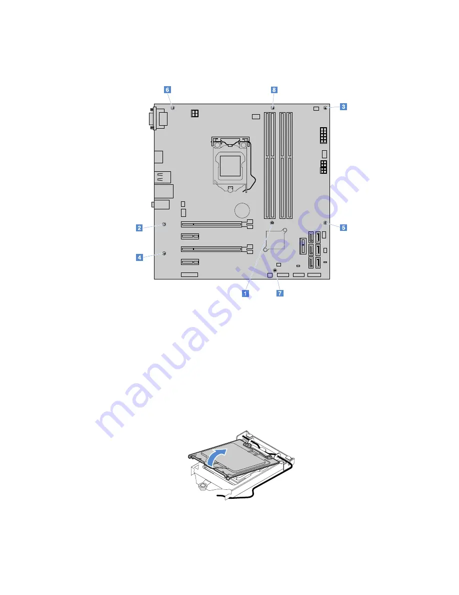
5. Remove the eight screws that secure the system board by following the numerical sequence as shown.
Then carefully lift the system board out of the chassis.
Figure 91. Removing the system board
6. Place the old system board on a clean, flat, and static-protective surface.
7. Note the orientation of the new system board and carefully place it into the chassis. Ensure that the
rear connectors on the system board are inserted into the corresponding holes in the rear panel. Then,
align the eight screws in the system board with those in the chassis, and install the eight screws in the
reverse sequence as you remove them.
8. Pivot the CPU socket cover as shown to remove it from the new system board.
Note:
Do not drop anything onto the CPU socket while it is exposed. The socket pins must be kept
as clean as possible.
Figure 92. Removing the CPU socket cover
9. Remove the CPU from the old system board, and install it onto the new system board. See “For service
technician only: replacing the CPU” on page 95.
.
99
Summary of Contents for ThinkServer TS150
Page 14: ...xii ThinkServer TS150 User Guide and Hardware Maintenance Manual ...
Page 18: ...4 ThinkServer TS150 User Guide and Hardware Maintenance Manual ...
Page 52: ...38 ThinkServer TS150 User Guide and Hardware Maintenance Manual ...
Page 116: ...102 ThinkServer TS150 User Guide and Hardware Maintenance Manual ...
Page 124: ...110 ThinkServer TS150 User Guide and Hardware Maintenance Manual ...
Page 136: ...122 ThinkServer TS150 User Guide and Hardware Maintenance Manual ...
Page 146: ...132 ThinkServer TS150 User Guide and Hardware Maintenance Manual ...
Page 147: ......
Page 148: ......


