background image

commercial and industrial environments to provide reasonable protection against interference with licensed
communication equipment.

Lenovo, Einsteinova 21, 851 01 Bratislava, Slovakia

Warning:

This is a Class A product. In a domestic environment this product may cause radio interference

in which case the user may be required to take adequate measures.

German Class A compliance statement

Deutschsprachiger EU Hinweis:

Hinweis für Geräte der Klasse A EU-Richtlinie zur Elektromagnetischen Verträglichkeit

Dieses Produkt entspricht den Schutzanforderungen der EU-Richtlinie 2014/30/EU (früher 2004/108/EC) zur
Angleichung der Rechtsvorschriften über die elektromagnetische Verträglichkeit in den EU-Mitgliedsstaaten
und hält die Grenzwerte der Klasse A der Norm gemäß Richtlinie.

Um dieses sicherzustellen, sind die Geräte wie in den Handbüchern beschrieben zu installieren und zu
betreiben. Des Weiteren dürfen auch nur von der Lenovo empfohlene Kabel angeschlossen werden.
Lenovo übernimmt keine Verantwortung für die Einhaltung der Schutzanforderungen, wenn das Produkt
ohne Zustimmung der Lenovo verändert bzw. wenn Erweiterungskomponenten von Fremdherstellern ohne
Empfehlung der Lenovo gesteckt/eingebaut werden.

Deutschland:

Einhaltung des Gesetzes über die elektromagnetische Verträglichkeit von Betriebsmittein

Dieses Produkt entspricht dem „Gesetz über die elektromagnetische Verträglichkeit von Betriebsmitteln“
EMVG (früher „Gesetz über die elektromagnetische Verträglichkeit von Geräten“). Dies ist die Umsetzung der
EMV EU Richtlinie 2014/30/EU (früher 2004/108/EC) in der Bundesrepublik Deutschland.

Zulassungsbescheinigung laut dem Deutschen Gesetz über die elektromagnetische Verträglichkeit
von Betriebsmitteln, EMVG vom 20. Juli 2007 (früher Gesetz über die elektromagnetische
Verträglichkeit von Geräten), bzw. der EMV EU Richtlinie 2014/30/EU (früher 2004/108/EC), für
Geräte der Klasse A.

Dieses Gerät ist berechtigt, in Übereinstimmung mit dem Deutschen EMVG das EG-Konformitätszeichen
- CE - zu führen. Verantwortlich für die Konformitätserklärung nach Paragraf 5 des EMVG ist die Lenovo
(Deutschland) GmbH, Meitnerstr. 9, D-70563 Stuttgart.

Informationen in Hinsicht EMVG Paragraf 4 Abs. (1) 4:

Das Gerät erfüllt die Schutzanforderungen nach EN 55024 und EN 55022 Klasse A.

Nach der EN 55022: „Dies ist eine Einrichtung der Klasse A. Diese Einrichtung kann im Wohnbereich
Funkstörungen verursachen; in diesem Fall kann vom Betreiber verlangt werden, angemessene Maßnahmen
durchzuführen und dafür aufzukommen.“

Nach dem EMVG: „Geräte dürfen an Orten, für die sie nicht ausreichend entstört sind, nur mit besonderer
Genehmigung des Bundesministers für Post und Telekommunikation oder des Bundesamtes für Post und
Telekommunikation betrieben werden. Die Genehmigung wird erteilt, wenn keine elektromagnetischen
Störungen zu erwarten sind.“ (Auszug aus dem EMVG, Paragraph 3, Abs. 4). Dieses Genehmigungsverfahren
ist nach Paragraph 9 EMVG in Verbindung mit der entsprechenden Kostenverordnung (Amtsblatt 14/93)
kostenpflichtig.

106

ThinkServer RS160 User Guide and Hardware Maintenance Manual

Summary of Contents for ThinkServer RS160

Page 1: ...ThinkServer RS160 User Guide and Hardware Maintenance Manual Machine Types 70TD 70TE 70TF and 70TG ...

Page 2: ...t Note Your server might look slightly different from the illustrations in this document To show the main parts clearly some of the illustrations do not show all components First Edition September 2016 Copyright Lenovo 2016 LIMITED AND RESTRICTED RIGHTS NOTICE If data or software is delivered pursuant to a General Services Administration GSA contract use reproduction or disclosure is subject to re...

Page 3: ... the ThinkServer EasyStartup program 35 Starting the ThinkServer EasyStartup program 36 Using the ThinkServer EasyStartup program on a Windows operating system 37 Configuring RAID 38 About RAID 38 RAID for your server 39 Configuring onboard SATA software RAID 40 Configuring advanced SATA or SAS hardware RAID 42 Configuring the Ethernet controllers 43 Chapter 5 Replacing hardware 45 Purchasing Thin...

Page 4: ...nt for ac power consumption for JEITA harmonics guideline 107 Japanese statement of compliance for products less than or equal to 20 A per phase for JEITA harmonics guideline 108 Eurasian compliance mark 108 Appendix B WEEE and recycling information 109 Important WEEE information 109 Recycling information for Japan 109 Recycling information for Brazil 110 Battery recycling information for Taiwan 1...

Page 5: ...hjeet julkaisu Lenovon verkkosivustosta ennen tuotteen käyttöä Avant d utiliser ce produit prenez connaissance des Safety Information Informations relatives à la sécurité multilingues sur le site Web Lenovo Πριν χρησιμοποιήσετε το προϊόν φροντίστε να διαβάσετε και να κατανοήσετε τις Safety Information Πληροφορίες ασφαλείας στο δικτυακό τόπο της Lenovo Vor Verwendung des Produkts sollten Sie die me...

Page 6: ...ti Lenovo Pred uporabo izdelka poskrbite da boste prebrali in razumeli razdelek Safety Information Varnostne informacije ki je na spletnem mestu Lenovo na voljo v več jezikih Antes de usar el producto asegúrese de leer y entender la sección Safety Information Información de seguridad multilingüe del sitio web de Lenovo Innan du använder den här produkten är det viktigt att du har läst och förstått...

Page 7: ...ess instructed otherwise in the installation and configuration procedures Connect and disconnect cables as described in the following table when installing moving or opening covers on this product or attached devices To connect To disconnect 1 Turn everything OFF 2 First attach all cables to devices 3 Attach signal cables to connectors 4 Attach power cords to outlets 5 Turn devices ON 1 Turn every...

Page 8: ...ss 3B laser diode Note the following Laser radiation when open Do not stare into the beam do not view directly with optical instruments and avoid direct exposure to the beam Statement 4 18 kg 39 7 lb 32 kg 70 5 lb 55 kg 121 2 lb 32 kg 70 5 lb 55 kg 121 2 lb 100 kg 220 5 lb CAUTION Use safe practices when lifting Statement 5 CAUTION The power control button on the device and the power switch on the...

Page 9: ...oors will not support the weight of the device Statement 8 CAUTION Never remove the cover on a power supply or any part that has the following label attached Hazardous voltage current and energy levels are present inside any component that has this label attached There are no serviceable parts inside these components If you suspect a problem with one of these parts contact a service technician Sta...

Page 10: ...ded on the rails Statement 14 CAUTION Some accessory or option board outputs exceed Class 2 or limited power source limits You must install the appropriate interconnecting cabling in accordance with your local electrical code requirements Statement 15 CAUTION The power control button on the device may put the device in standby mode instead of turning off the device In addition the device might hav...

Page 11: ...ements Use 1 3 mm2 or 16 American Wire Gauge AWG copper conductor only not exceeding 3 meters in length Torque the wiring terminal screws to 1 4 newton meters or 12 inch pounds Provide a readily available approved and rated disconnect device in the field wiring Statement 17 CAUTION This product contains a Class 1M laser Do not view directly with optical instruments Statement 18 CAUTION Do not plac...

Page 12: ...her you can continue without first correcting the problem Consider these conditions and the safety hazards they present Electrical hazards especially primary power primary voltage on the frame can cause serious or fatal electrical shock Explosive hazards such as a damaged Cathode Ray Tube CRT monitor or a bulging capacitor Mechanical hazards such as loose or missing hardware To determine whether t...

Page 13: ...r worn frayed or pinched cables 9 Check that the power supply cover fasteners screws or rivets have not been removed or tampered with Grounding requirements Electrical grounding of the server is required for operator safety and correct system function Proper grounding of the electrical outlet can be verified by a certified electrician Copyright Lenovo 2016 xi ...

Page 14: ...xii ThinkServer RS160 User Guide and Hardware Maintenance Manual ...

Page 15: ...the telephone number for your country or region is not listed contact your Lenovo reseller or Lenovo marketing representative Most up to date information about the server http www lenovo com thinkserver Latest technical information http www lenovo com support Instructions on how to register your server with Lenovo Follow the instructions at http www lenovo com register When you register your serve...

Page 16: ...etter to customers This is a multilingual letter to customers which tells customers that Lenovo is undertaking a paperless electronic documentation initiative to protect environment This letter also provides information about how to contact Lenovo if you require a printed version of any electronic documents Electronic documents You can find the following electronic documents at https support lenov...

Page 17: ...onfigure and maintain your server ThinkServer Management Module User Guide English only This document provides information about server remote management MegaRAID SAS Software User Guide English only This document provides information about Redundant Array of Independent Disks RAID and how to use the utility programs to configure monitor and maintain your server RAID and related devices Note Refer...

Page 18: ...4 ThinkServer RS160 User Guide and Hardware Maintenance Manual ...

Page 19: ...tall the operating system and device drivers See Using the ThinkServer EasyStartup program on page 35 and Configuring RAID on page 38 8 Install any additional drivers required for added features Refer to the instructions that come with the hardware option 9 Configure Ethernet settings in the operating system by referring to the operating system help You can skip this step if the operating system w...

Page 20: ...nel to start an orderly shutdown of the operating system and turn off the server if your operating system supports this feature If your server stops responding and you cannot turn it off press and hold the power button on the front panel for four seconds or more If you still cannot turn off the server disconnect all power cords from the server You also can use the related TMM feature to remotely t...

Page 21: ...he RAS features help you to ensure the integrity of the data stored on the server the availability of the server when you need it and the ease with which you can diagnose and correct problems Dimension and weight Width without rack handles 438 5 mm 17 26 inches Depth 393 7 mm 15 5 inches Height 43 2 mm 1 7 inches Range of product weight without package 6 2 kg 13 67 lb 7 6 kg 16 76 lb Electrical in...

Page 22: ...m SATA optical drive available on some models Expansion slots The server has one Peripheral Component Interconnect Express PCIe card slot on the riser card assembly For more information see Rear view of the server on page 14 Input Output I O features Front panel Two USB 2 0 connectors Rear panel Four USB 3 0 connectors Serial connector Video graphics array VGA connector Three RJ 45 Ethernet connec...

Page 23: ...platform management subsystem consists of the integrated TMM communication buses sensors the BIOS and server management firmware The subsystem is responsible for error reporting system power control thermal monitoring system fan control and other management features The TMM provides system management and monitoring features based on the IPMI 2 0 specification IPMI helps lower the overall costs of ...

Page 24: ...nd installing supported Microsoft Windows and Linux operating systems and device drivers on your server This program is provided with your server on a self starting bootable ThinkServer EasyStartup DVD The user guide for the program is also on the DVD and can be accessed directly from the program interface For more information see Using the ThinkServer EasyStartup program on page 35 BIOS and TMM u...

Page 25: ...ons This topic provides information to help you locate your server components Machine type model and serial number label When you contact Lenovo for help the machine type model and serial number information helps service technicians to identify your server and provide faster service Locate the machine type model and serial number label on the server as shown in the following illustration ID MT M X...

Page 26: ...status LED 2 System ID button with ID LED 3 HDD status LED 4 Network status LED 5 System error LED 6 7 USB 2 0 connectors 1 Power button with power status LED You can press the power button to turn on or turn off the server The power status LED helps you to determine the current power status Status Description Green The server is on Off The server is off 2 System ID button with ID LED When you pre...

Page 27: ...or 2 on the rear panel of the server Status Description Green The server is connected to a LAN Off The server is disconnected from a LAN Blinking green The LAN is connected and active 5 System error LED The system error LED helps you to determine if there are any system errors Status Description Yellow The server has an error Off The server is off or the server is on and working correctly 6 7 USB ...

Page 28: ... Serial connector Used to attach a device that uses a 9 pin serial connector 3 Ethernet connector 1 RJ 45 4 Ethernet connector 2 RJ 45 Used to attach an Ethernet cable for a LAN Each Ethernet connector has two status LEDs to help you identify the Ethernet connectivity activity and connection speed Figure 5 Ethernet status LEDs Ethernet status LED Status Description Yellow The server is connected t...

Page 29: ...PCIe card slot for the card installed on the riser card assembly This slot is used to install a PCIe card such as a RAID card or a ThinkServer Host Bus Adapter HBA 6 ID LED When you press the ID button on the front panel the ID LEDs on both the front and rear of the server are lit to help you locate the server among other servers You also can turn on the ID LEDs using a remote management program f...

Page 30: ... with one of the following drive configurations Four 2 5 inch HDDs or SSDs Two 3 5 inch HDDs Note Depending on the model your server might look slightly different from the illustration in this topic Figure 7 Server components 16 ThinkServer RS160 User Guide and Hardware Maintenance Manual ...

Page 31: ...rs or by service technicians under certain terms of the applicable warranty service type for your country or region 3 Non CRUs Parts must be installed or replaced only by trained service technicians Before servicing a Lenovo product ensure that you read and understand Read this first safety information on page iii Use only parts provided by Lenovo for replacement For a complete listing of FRU info...

Page 32: ...3 connector Used to connect to a ThinkServer RAID 520i upgrade key Lenovo ThinkServer RAID 720i PCIe Adapter The RAID 720i Adapter provides advanced SATA SAS hardware RAID functions The following illustration shows the connectors on the adapter Figure 9 ThinkServer RAID 720i PCIe Adapter Connector Description 1 Connector 0 Used to connect the mini SAS signal cable 2 Connector 1 Used to connect the...

Page 33: ... to the system board on page 19 Connecting the 2 5 inch hard disk drives to the RAID card on page 20 Connecting the 3 5 inch hard disk drives to the system board on page 22 Connecting the 3 5 inch hard disk drives to the RAID card on page 22 Connecting the slim optical drive on page 23 Connecting the 2 5 inch hard disk drives to the system board To connect the 2 5 inch HDDs to the system board do ...

Page 34: ...DDs 3 Route the cables using the cable clips or ties in the chassis Connecting the 2 5 inch hard disk drives to the RAID card Note If you are connecting the 2 5 inch HDDs to another type of ThinkServer HBA the procedure is similar To connect the 2 5 inch HDDs to the RAID card do the following 20 ThinkServer RS160 User Guide and Hardware Maintenance Manual ...

Page 35: ...connected to the power cables from the power supply 0 1 2 3 Figure 12 Connecting the mini SAS cable to the RAID card 2 Install the RAID card to the riser card assembly See Installing the PCIe card on page 56 3 Connect the mini SAS cable to the HDDs and any two of the power cable connectors as shown Figure 13 Connecting the mini SAS cable to the HDDs and power cable connectors 4 Route the cables us...

Page 36: ... as shown HDD0 HDD1 HDD0 HDD1 Figure 14 Connecting the SATA cables and power cable for the 3 5 inch HDDs 2 Route the cables using the cable clips or ties in the chassis Connecting the 3 5 inch hard disk drives to the RAID card Note If you are connecting the 3 5 inch HDDs to another type of ThinkServer HBA the procedure is similar To connect the 3 5 inch HDDs to the RAID card do the following 22 Th...

Page 37: ...0 1 Figure 15 Connecting the mini SAS cable to the RAID card 2 Install the RAID card to the riser card assembly See Installing the PCIe card on page 56 3 Connect the mini SAS cable to the HDDs and any one of the power cable connectors as shown Figure 16 Connecting the mini SAS cable to the HDDs and power cable connector 4 Route the cables using the cable clips or ties in the chassis Connecting the...

Page 38: ...optical drive as shown Note Depending on the configuration the server might look slightly different from the following illustration ODD Figure 17 Connecting the slim optical drive 2 Route the cables using the cable clips or ties in the chassis 24 ThinkServer RS160 User Guide and Hardware Maintenance Manual ...

Page 39: ...and SATA connector for HDD 2 lower 10 SATA connector for ODD upper and SATA connector for HDD 3 lower 11 Front panel connector 1 12 Front panel connector 2 13 M 2 SSD connector 14 USB 2 0 connector 15 System fan 3 connector 16 TPM connector 17 Riser card assembly slot 18 Clear CMOS jumper 19 Coin cell battery socket 1 ME recovery jumpers Used to recover the manageability engines 2 8 pin power conn...

Page 40: ...that is used to enhance server security 17 Riser card assembly slot Used to install the riser card assembly 18 Clear CMOS jumper Used to clear CMOS and turn the BIOS settings into the factory default settings To clear CMOS do the following 1 Prepare your server See Preparing your server in advance on page 47 2 Do one of the following Remove the coin cell battery for a few minutes Then reinstall it...

Page 41: ...coin cell battery Your server has a special type of memory that maintains the date time and configuration information for built in features The coin cell battery keeps the information active when you turn off the server Chapter 3 Product overview 27 ...

Page 42: ...28 ThinkServer RS160 User Guide and Hardware Maintenance Manual ...

Page 43: ...pens If you have set a password type the correct password to enter the Setup Utility program For password information see Using passwords on page 32 Setup Utility program interface Depending on the BIOS version of your server some menu or item information might differ slightly from the information in this topic Notes The default settings already are optimized for you Use the default value for any ...

Page 44: ...orm Services SPS information Super IO Configuration View and set super I O configuration parameters Serial Port Console Redirection View and set Serial Port Console Redirection configuration parameters H W Monitor View the status of the hardware on your server Trust Computing View and set TPM configuration parameters Intel TXT Information View and set the Intel Trusted Execution Technology TXT sup...

Page 45: ...e displayed on the menu only if the server supports the corresponding features The Server Mgmt menu contains the following items For more information enter the corresponding items and refer to the instructions on the screen Menu item Description System Event Log View and set system event log parameters BMC Network Configuration View and set BMC configuration parameters Exit menu After you finish v...

Page 46: ... the supervisor password has higher authority Always When Always is selected the server cannot be used until a valid password is typed in Note If both the supervisor password and user password are set you can type either password to use the server However you must use your supervisor password to change any configuration settings Password considerations For security reasons it is recommended that y...

Page 47: ... menu select Trust Computing Security device support Ensure that Security device support is set to Enable 3 When Security device support is set to Enabled the TPM State item is displayed Set TPM State to Enabled 4 Press F10 to save settings and exit the Setup Utility program The server will restart in order to enable the TPM function Selecting a startup device If your server does not start up from...

Page 48: ... available for download on the Lenovo Web site at http www lenovo com support You can update the server firmware by downloading an update package and following the instructions on the Web page Updating flashing the BIOS This topic provides instructions on how to update flash the BIOS Notes Update the BIOS on your server only if the newer BIOS version specifically solves a problem you have We do no...

Page 49: ... Lenovo Customer Support Center See Calling for service on page 102 Using the ThinkServer EasyStartup program The ThinkServer EasyStartup program simplifies the process of configuring RAID and installing supported Windows and Linux operating systems and device drivers on your server The program works with your Windows or Linux operating system installation disc to automate the process of installin...

Page 50: ...yboard layout you will be using with the program Note The supported languages and keyboard layouts for the ThinkServer EasyStartup program are German English Spanish French Italian Dutch Turkish and Japanese Your ThinkServer EasyStartup DVD might be English only In this case the keyboard layout should be English 3 After selecting the language and keyboard layout click OK Then you will see one or m...

Page 51: ...orer 6 0 Web browser or a later version installed Enter the operating system and insert the ThinkServer EasyStartup DVD into an internal or external optical drive The DVD starts automatically in most environments If the DVD fails to start open the launch exe file located in the root directory of the DVD Note You should read and accept the Lenovo License Agreement when prompted You can do the follo...

Page 52: ...issing data from the remaining drives The following list describes some of the most commonly used RAID levels RAID 0 block level striping without parity or mirroring Simple stripe sets are normally referred to as RAID 0 RAID 0 uses striping to provide high data throughput especially for large files in an environment that does not require fault tolerance RAID 0 has no redundancy and it provides imp...

Page 53: ...es in each RAID virtual drive in the span The RAID 1 virtual drives must have the same stripe size RAID 10 provides high data throughput and complete data redundancy but uses a larger number of spans RAID 10 requires a minimum number of four HDDs and also requires an even number of drives for example six HDDs or eight HDDs RAID 50 a combination of RAID 0 and RAID 5 RAID 50 uses distributed parity ...

Page 54: ... 1 5 and 10 for ThinkServer RAID 720i PCIe Adapter by default To activate RAID 6 level you need to install a Thunderbolt Memory Module on the RAID card For more information see Configuring advanced SATA or SAS hardware RAID on page 42 Notes For server models with SAS hard disk drives a RAID card must be installed The ThinkServer EasyStartup program simplifies the process of configuring supported R...

Page 55: ...d select Exit and press Enter Deleting RAID volumes This section describes how to use the Intel Rapid Storage Technology enterprise option ROM configuration utility to delete RAID volumes To delete RAID volumes do the following 1 Press Ctrl I when prompted to enter the Intel Rapid Storage Technology enterprise option ROM configuration utility during system startup 2 Use the up and down arrow keys ...

Page 56: ...spare same slot For the SUSE Linux Enterprise Server 11 4 operating system do the following 1 Add the following line to the end of the etc mdadm conf file POLICY domain DOMAIN path metadata imsm action spare same slot 2 Run the following commands as a root user chkconfig s mdadmd on etc init d mdadmd start Configuring advanced SATA or SAS hardware RAID Some server models come with a required RAID ...

Page 57: ...page Instructions for configuring SATA SAS hardware RAID For instructions on how to configure and manage the advanced SATA or SAS hardware RAID refer to the MegaRAID SAS Software User Guide This guide is available on the Lenovo Support Web site at http www lenovo com support Configuring the Ethernet controllers Two Ethernet controllers are integrated on the system board They provide two ports for ...

Page 58: ...44 ThinkServer RS160 User Guide and Hardware Maintenance Manual ...

Page 59: ...ure that you read and understand the multilingual safety instructions and the Lenovo Limited Warranty LLW on the Lenovo Web site at https support lenovo com documents LNVO DOCS Reading and understanding the safety instructions reduces the risk of personal injury and damage to your product When you install your new server take the opportunity to download and apply the most recent firmware updates T...

Page 60: ... circuitry Do not leave the device where others can handle and possibly damage the device Before you replace a new part touch the static protective package containing the new part to an unpainted metal part of the server for at least two seconds This reduces static electricity from the package and your body Remove the new part from the static protective package and directly install it in the serve...

Page 61: ...ack remove or extend the server from the rack before removing or installing hardware Depending on the rail type do one of the following If the server is installed in a rack using static rails turn off the server and remove it from the rack Place the server on a flat clean and static protective surface See the documentation that comes with the rail kit If the server is installed in a rack using sli...

Page 62: ... server Operating the server with the server cover removed for more than 30 minutes might damage server components Removing and installing hardware This topic provides instructions on how to remove and install hardware for your server You can expand the capabilities of your server by adding new hardware devices such as memory modules PCIe card or other server options and maintain your server by re...

Page 63: ...stalled in a rack remove the server from the rack See Removing or extending the server from the rack on page 47 2 On each side of the server remove the two screws 1 that secure the rack handle and then remove the rack handle from the chassis Figure 20 Removing the rack handles Installing the rack handles To install the rack handles do the following Chapter 5 Replacing hardware 49 ...

Page 64: ...baffle To access some server components on the system board you must remove the air baffle To ensure proper cooling and airflow you must reinstall the air baffle before turning on the server Removing the air baffle on page 50 Installing the air baffle on page 51 Removing the air baffle To remove the air baffle do the following 1 Prepare your server See Preparing your server in advance on page 47 5...

Page 65: ...the air baffle Note the orientation of the air baffle and place it above the heat sink Then lower the air baffle into the chassis until it is secured into position Figure 23 Installing the air baffle To complete the parts replacement go to Completing the parts replacement on page 95 Chapter 5 Replacing hardware 51 ...

Page 66: ...rews from the system board using the following method to avoid any possible damage to the system board a Partially remove screw 1 then completely remove screw 2 and then return to screw 1 and completely remove it b Partially remove screw 3 then completely remove screw 4 and then return to screw 3 and completely remove it Note The four screws are integrated parts of the heat sink Do not try to remo...

Page 67: ...e 3 Place the heat sink on the system board so that the four screws on the heat sink are inserted into the corresponding holes in the system board 4 Install the four screws to secure the heat sink on the system board It is recommended that you carefully install the four screws using the following method to avoid any possible damage to the system board a Partially tighten screw 1 then firmly tighte...

Page 68: ... When you install memory modules with different capacity install the memory module that has the highest capacity first Installation order The following illustration shows the installation order for the four memory slots Install memory modules in the numerical order as shown Figure 26 Memory module installation order Removing the memory module Note The memory modules are extremely sensitive to ESD ...

Page 69: ...er in advance on page 47 2 Locate an appropriate memory slot on the system board by referring to the memory module installation rules in Memory module on page 53 If a filler is installed in the slot remove the filler 3 Touch the static protective package that contains the new memory module to any unpainted surface on the outside of the server Then take the new memory module out of the package Note...

Page 70: ...e card might fit tightly into the PCIe card slot If necessary alternate moving each side of the PCIe card a small and equal amount until it is completely removed from the slot Figure 29 Removing the PCIe card 3 Disconnect any cables from the PCIe card 4 Install a new PCIe card to replace the old one or install a PCIe card slot bracket to cover the place See Installing the PCIe card on page 56 5 If...

Page 71: ...se you later remove the PCIe card and need the bracket to cover the place Figure 30 Removing the PCIe card slot bracket 3 Touch the static protective package that contains the new PCIe card to any unpainted surface on the outside of the server Then take the new PCIe card out of the package Note Carefully handle the PCIe card by its edges 4 Connect any cables to the PCIe card if necessary See Conne...

Page 72: ...pleting the parts replacement on page 95 To install a required device driver for the PCIe card go to the Lenovo Support Web site at http www lenovo com support Download the PCIe card driver and the readme file and follow the instructions in the readme file to install the driver Riser card Removing the riser card on page 58 Installing the riser card on page 59 Removing the riser card To remove the ...

Page 73: ...ve the riser card Figure 33 Removing the riser card 5 If you are instructed to return the old riser card follow all packaging instructions and use any packaging materials that are supplied to you for shipping To complete the parts replacement go to Completing the parts replacement on page 95 Installing the riser card To install a new riser card do the following 1 Prepare your server See Preparing ...

Page 74: ...orresponding ones in the bracket Then install the two screws to secure the riser card to the bracket Figure 34 Installing the riser card 6 Position the riser card assembly on the chassis and align it with the riser card assembly slot on the system board Align the screw hole in the riser card assembly with the corresponding hole in the chassis Then carefully press the riser card assembly straight d...

Page 75: ...posure to hazardous laser radiation There are no serviceable parts inside the device Use of controls or adjustments or performance of procedures other than those specified herein might result in hazardous radiation exposure DANGER Some laser products contain an embedded Class 3A or Class 3B laser diode Note the following Laser radiation when open Do not stare into the beam do not view directly wit...

Page 76: ...ou are instructed to return the old slim optical drive follow all packaging instructions and use any packaging materials that are supplied to you for shipping To complete the parts replacement go to Completing the parts replacement on page 95 Installing the slim optical drive To install the slim optical drive do the following 1 Prepare your server See Preparing your server in advance on page 47 2 ...

Page 77: ...l to cover the place Figure 37 Removing the optical drive bay metal bezel b Loosen the thumbscrew 1 that secures the slim optical drive retainer and then remove the retainer from the chassis Note The thumbscrew is an integrated part of the slim optical drive retainer Do not try to remove the thumbscrew from the retainer Figure 38 Removing the slim optical drive retainer Chapter 5 Replacing hardwar...

Page 78: ...front of the server Figure 39 Installing the slim optical drive 5 Attach the slim optical drive retainer to the side of the slim optical drive Then tighten the thumbscrew 1 to secure the slim optical drive retainer Figure 40 Installing the slim optical drive retainer 6 Connect the cables to the rear of the slim optical drive See Connecting the slim optical drive on page 23 64 ThinkServer RS160 Use...

Page 79: ...moved it See Installing the PCIe card on page 56 5 If you are instructed to return the old M 2 SSD follow all packaging instructions and use any packaging materials that are supplied to you for shipping To complete the parts replacement go to Completing the parts replacement on page 95 Installing the M 2 solid state drive To install the M 2 SSD do the following 1 Prepare your server See Preparing ...

Page 80: ... 520i PCIe Adapter installed you can purchase a RAID 520i key and install it to the J3 connector on the RAID card For information about connectors on the RAID card see RAID card on page 17 Removing the RAID 520i key on page 66 Installing the RAID 520i key on page 67 Removing the RAID 520i key Notes If you remove the RAID 520i key the hardware RAID 5 will be disabled Removing the RAID 520i key migh...

Page 81: ...ore you might need to reconfigure RAID for your server For information about configuring hardware RAID refer to the MegaRAID SAS Software User Guide This guide is available on the Lenovo Support Web site at http www lenovo com support Installing the RAID 520i key To install the RAID 520i key do the following 1 Prepare your server See Preparing your server in advance on page 47 2 Remove the Lenovo ...

Page 82: ...de is available on the Lenovo Support Web site at http www lenovo com support Thunderbolt Memory Module Removing the Thunderbolt Memory Module on page 68 Installing the Thunderbolt Memory Module on page 69 This topic applies only to Lenovo ThinkServer RAID 720i PCIe Adapter that supports the Thunderbolt Memory Module The Thunderbolt Memory Module works as the cache memory of the installed Lenovo T...

Page 83: ...aterials that are supplied to you for shipping 5 Reinstall the Lenovo ThinkServer RAID 720i PCIe Adapter See Installing the PCIe card on page 56 To complete the parts replacement go to Completing the parts replacement on page 95 Installing the Thunderbolt Memory Module To install the Thunderbolt Memory Module do the following 1 Prepare your server See Preparing your server in advance on page 47 2 ...

Page 84: ...See Installing the PCIe card on page 56 To complete the parts replacement go to Completing the parts replacement on page 95 Slim optical drive bracket Removing the slim optical drive bracket on page 70 Installing the slim optical drive bracket on page 71 Removing the slim optical drive bracket To remove the slim optical drive bracket do the following 1 Prepare your server See Preparing your server...

Page 85: ...e slim optical drive bracket To install the slim optical drive bracket do the following 1 Position the bracket in the chassis align the four slots in the bracket with the mounting studs on the chassis and then slide the bracket to the front of the server until the pin 1 is snapped into position Figure 48 Installing the slim optical drive bracket 2 Reinstall the slim optical drive if you have remov...

Page 86: ...owing the order of the HDD bays as well as the order from the lowest capacity to the highest capacity Removing a 2 5 inch hard disk drive To remove a 2 5 inch HDD do the following 1 Prepare your server See Preparing your server in advance on page 47 2 Locate the appropriate 2 5 inch HDD that you want to remove If you want to remove the 2 5 inch HDDs that are installed under the slim optical drive ...

Page 87: ...Installing the slim optical drive bracket on page 71 To complete the parts replacement go to Completing the parts replacement on page 95 Installing a 2 5 inch hard disk drive To install a 2 5 inch HDD do the following 1 Prepare your server See Preparing your server in advance on page 47 2 If you want to install a 2 5 inch HDD under the slim optical drive bracket remove the slim optical drive brack...

Page 88: ... the bracket 5 Align the four screw holes in the HDD with the corresponding holes in the bracket Then install the four screws to secure the HDD to the bracket Figure 52 Installing the screws to secure the 2 5 inch HDD to bracket 74 ThinkServer RS160 User Guide and Hardware Maintenance Manual ...

Page 89: ...isk drive HDD installation rules Follow the order of the HDD bays when installing an HDD For RAID configuration the HDDs must be the same type with the same capacity if they are within a single RAID array For more information see Configuring RAID on page 38 For HDDs with different capacities install the HDD by following the order of the HDD bays as well as the order from the lowest capacity to the...

Page 90: ...ng the 3 5 inch HDD from the bracket 6 If you are instructed to return the old HDD follow all packaging instructions and use any packaging materials that are supplied to you for shipping 7 Reinstall the slim optical drive bracket if you have removed it See Installing the slim optical drive bracket on page 71 To complete the parts replacement go to Completing the parts replacement on page 95 Instal...

Page 91: ...our server See Removing a 2 5 inch hard disk drive on page 72 4 Install the new 3 5 inch HDD into the bracket Figure 56 Installing the 3 5 inch HDD into the bracket 5 Align the four screw holes in the HDD with the corresponding holes in the bracket Then install the four screws to secure the HDD to the bracket Figure 57 Installing the screws to secure the 3 5 inch HDD to bracket Chapter 5 Replacing...

Page 92: ...nstalling the slim optical drive bracket on page 71 To complete the parts replacement go to Completing the parts replacement on page 95 System fan Removing a system fan on page 78 Installing a system fan on page 79 CAUTION Hazardous moving parts Keep fingers and other body parts away Removing a system fan To remove a system fan do the following 1 Prepare your server See Preparing your server in ad...

Page 93: ...stem fan See Installing a system fan on page 79 7 If you are instructed to return the old system fan follow all packaging instructions and use any packaging materials that are supplied to you for shipping Installing a system fan To install a system fan do the following 1 Touch the static protective package that contains the new system fan to any unpainted surface on the outside of the server Then ...

Page 94: ...usted Computing Group TCG to provide a hardware method of data encryption It stores passwords encryption keys and digital certificates to help provide security solutions and protect the server Removing the TPM on page 80 Installing the TPM on page 81 Removing the TPM To remove the TPM do the following 1 Prepare your server See Preparing your server in advance on page 47 2 Locate the TPM connector ...

Page 95: ...ing the parts replacement on page 95 Installing the TPM To install the TPM do the following 1 Prepare your server See Preparing your server in advance on page 47 2 If there is a PCIe card installed it might block your access to the TPM connector In this case remove the PCIe card See Removing the PCIe card on page 56 3 If there is an old TPM installed remove the old TPM See Removing the TPM on page...

Page 96: ...erver The coin cell battery normally requires no charging or maintenance throughout its life however no battery lasts forever If the coin cell battery fails the date time and configuration information including passwords are lost and an error message is displayed when you turn on the server Removing the coin cell battery on page 83 Installing the coin cell battery on page 83 DANGER Danger of explo...

Page 97: ... 25 3 Remove the coin cell battery Figure 63 Removing the coin cell battery 4 Install a new coin cell battery See Installing the coin cell battery on page 83 5 Dispose of the failing battery as required by local ordinances or regulations Installing the coin cell battery To install a new coin cell battery and configure the server do the following 1 Install the new coin cell battery to the server Fi...

Page 98: ...e front panel board Then carefully remove the front panel board from the chassis Figure 65 Removing the front panel board 5 Record the cable routing and cable connections Then disconnect all the cables from the front panel board 6 If you are instructed to return the old front panel board follow all packaging instructions and use any packaging materials that are supplied to you for shipping Install...

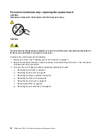
Page 99: ... 73 and Installing a 3 5 inch hard disk drive on page 76 To complete the parts replacement go to Completing the parts replacement on page 95 For service technician only replacing the ThinkServer RAID Super Capacitor Module The ThinkServer RAID Super Capacitor Module protects the cache memory on the installed ThinkServer RAID card To replace the ThinkServer RAID Super Capacitor Module do the follow...

Page 100: ...racket 4 Gently press the two tabs on the ThinkServer RAID Super Capacitor Module bracket and remove the bracket at the same time Note Skip this step if you are just installing a new ThinkServer RAID Super Capacitor Module instead of both the ThinkServer RAID Super Capacitor Module and its bracket Figure 68 Removing the ThinkServer RAID Super Capacitor Module bracket from the chassis 86 ThinkServe...

Page 101: ...nting studs on the chassis pass through the corresponding holes in the bracket Then move the bracket as shown until it is secured on the chassis Figure 69 Installing the ThinkServer RAID Super Capacitor Module bracket into the chassis 7 Note the orientation of the ThinkServer RAID Super Capacitor Module and then install it into the bracket Figure 70 Installing the ThinkServer RAID Super Capacitor ...

Page 102: ...l attached Hazardous voltage current and energy levels are present inside any component that has this label attached There are no serviceable parts inside these components If you suspect a problem with one of these parts contact a service technician To replace the power supply assembly do the following 1 Prepare your server See Preparing your server in advance on page 47 2 Disconnect the power cab...

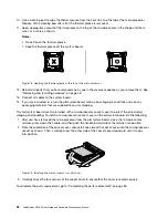
Page 103: ...ly assembly follow all packaging instructions and use any packaging materials that are supplied to you for shipping To complete the parts replacement go to Completing the parts replacement on page 95 For service technician only replacing the microprocessor CAUTION The heat sink and the microprocessor might be very hot Turn off the server and wait three to five minutes to let the server cool before...

Page 104: ...sor socket Notes Do not touch the gold contacts on the bottom of the microprocessor Do not drop anything onto the microprocessor socket while it is exposed The socket pins must be kept as clean as possible Figure 73 Removing the microprocessor 5 Touch the static protective package that contains the new microprocessor to any unpainted surface on the outside of the server Then remove the new micropr...

Page 105: ...the microprocessor 8 Gently close the microprocessor retainer Press down the handle and then push the handle inward to lock the retainer into position and secure the new microprocessor in the socket Figure 75 Securing the microprocessor in the socket 9 Reinstall the heat sink See Installing the heat sink on page 53 10 Reinstall the air baffle See Installing the air baffle on page 51 11 If you are ...

Page 106: ...ing your server in advance on page 47 2 Record the component locations cable connections and cable routing in the server Then disconnect all cables from the system board 3 To access the system board remove the following components in order a Removing the air baffle on page 50 b Removing the heat sink on page 52 c Removing the memory module on page 54 d Removing the PCIe card on page 56 e Removing ...

Page 107: ...he chassis Ensure that the rear connectors on the system board are inserted into the corresponding holes in the rear panel Then align the eight screw holes in the system board with those in the chassis and install the eight screws in the reverse sequence as you remove them 8 Pivot the microprocessor socket cover as shown to remove it from the new system board Note Do not drop anything onto the mic...

Page 108: ...aterials that are supplied to you for shipping The old system board must be returned with a microprocessor socket cover to protect the pins during shipping and handling To install a microprocessor socket cover on the old system board do the following 1 After you have removed the microprocessor from the old system board close the microprocessor retainer press down the handle and then push the handl...

Page 109: ...s clear of the hinges and sides of the chassis to avoid interference with reinstalling the air baffle and the server cover The following illustration shows an example of the cable routing in the chassis with two 3 5 inch HDDs For instructions on connecting cables for HDDs slim optical drive and RAID card see Connecting the cables on page 19 Figure 80 An example of cable routing server models with ...

Page 110: ...cumentation that comes with the rail kit 6 Reconnect external cables and power cords to the server See Rear view of the server on page 14 to identify the connectors on the rear panel of the server Attention To avoid component damage connect the power cords last 7 Update the server configuration Download and install the latest device drivers http www lenovo com support Update the BIOS configuration...

Page 111: ...m could be solved 6 View the system event log to diagnose problems See Viewing the system event log on page 97 7 Turn on the server and press Esc as soon as you see the logo screen to view any diagnostic messages 8 Refer to Basic troubleshooting tables on page 98 and follow the instructions for the type of problem you are experiencing If the basic troubleshooting information does not help you reso...

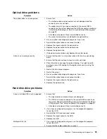
Page 112: ...only this action step is reserved for a trained service technician and must be performed only by a trained service technician ThinkServer EasyStartup program problems Symptom Action The ThinkServer EasyStartup DVD does not start Ensure that the server supports the ThinkServer EasyStartup program and has a bootable DVD drive installed or a bootable external DVD drive attached Ensure that you have s...

Page 113: ...atched 3 Check the disc or package for regional coding You might need to purchase a disc with coding for the region where you are using the product 4 Restart the disc player program 5 Restart the server 6 Run any optical drive diagnostic programs if you have 7 Reinstall the optical drive and reconnect cables 8 Replace the signal cable for the optical drive 9 Replace the optical drive Hard disk dri...

Page 114: ...e system firmware is up to date 2 If you have any diagnostic programs run the diagnostic programs to test the memory modules 3 Reinstall the memory modules 4 Replace the suspect memory modules 5 Trained service technician only Replace the system board USB device problems Symptom Action A USB device does not work 1 Ensure that The USB cable is securely connected to the server If the USB device is c...

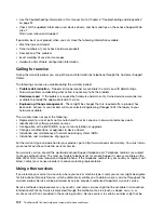
Page 115: ...operating system or software program ThinkServer Web site The ThinkServer Web site provides up to date information and services to help you buy use upgrade and maintain your server You can visit the ThinkServer Web site at http www lenovo com thinkserver Lenovo Support Web site Technical support information is available on the Lenovo Support Web site at http www lenovo com support This Web site is...

Page 116: ...arranted Lenovo parts Identification of software problem sources Configuration of the UEFI BIOS as part of an installation or upgrade Changes modifications or upgrades to device drivers Installation and maintenance of network operating systems NOS Installation and maintenance of programs For the warranty type and duration for your product go to http www lenovo com warranty You must retain your pro...

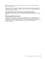
Page 117: ...d Windows product refer to the Microsoft Product Support Services Web site at http support microsoft com directory or you can contact the Customer Support Center Some fees might apply Purchasing additional services During and after the warranty period you can purchase additional services such as support for hardware operating systems and programs network setup and configuration services upgraded o...

Page 118: ...104 ThinkServer RS160 User Guide and Hardware Maintenance Manual ...

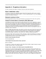
Page 119: ... any radio or television interference caused by using other than specified or recommended cables and connectors or by unauthorized changes or modifications to this equipment Unauthorized changes or modifications could void the user s authority to operate the equipment This device complies with Part 15 of the FCC Rules Operation is subject to the following two conditions 1 this device may not cause...

Page 120: ...setz über die elektromagnetische Verträglichkeit von Geräten Dies ist die Umsetzung der EMV EU Richtlinie 2014 30 EU früher 2004 108 EC in der Bundesrepublik Deutschland Zulassungsbescheinigung laut dem Deutschen Gesetz über die elektromagnetische Verträglichkeit von Betriebsmitteln EMVG vom 20 Juli 2007 früher Gesetz über die elektromagnetische Verträglichkeit von Geräten bzw der EMV EU Richtlini...

Page 121: ...ance statement Lenovo product service information for Taiwan Japan VCCI Class A statement This is a Class A product based on the standard of the Voluntary Control Council for Interference VCCI If this equipment is used in a domestic environment radio interference may occur in which case the user may be required to take corrective actions Japanese statement for ac power consumption for JEITA harmon...

Page 122: ...Japanese statement of compliance for products less than or equal to 20 A per phase for JEITA harmonics guideline Eurasian compliance mark 108 ThinkServer RS160 User Guide and Hardware Maintenance Manual ...

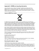
Page 123: ...EEE as unsorted municipal waste but use the collection framework available to them for the return recycle and recovery of WEEE and to minimize any potential effects of EEE on the environment and human health due to the presence of hazardous substances Lenovo electrical and electronic equipment EEE may contain parts and components which at end of life might qualify as hazardous waste EEE and waste ...

Page 124: ...omputer clock while the computer is off or disconnected from the main power source If you need to replace it with a new one contact your place of purchase or contact Lenovo for service If you need to dispose of a disused lithium battery insulate it with vinyl tape contact your place of purchase or an industrial waste disposal operator and follow their instructions Disposal of a lithium battery mus...

Page 125: ...ccumulators on the environment and human health due to the potential presence of hazardous substances Before placing electrical and electronic equipment EEE in the waste collection stream or in waste collection facilities the end user of equipment containing batteries and or accumulators must remove those batteries and accumulators for separate collection Disposing of lithium batteries and battery...

Page 126: ...al or batteries outside the United States go to http www lenovo com recycling or contact your local waste disposal facility Requirement for batteries containing perchlorate The following statement applies to users in the state of California U S A California Perchlorate Information Products containing manganese dioxide lithium coin cell batteries may contain perchlorate Perchlorate Material special...

Page 127: ...U on the restriction of the use of certain hazardous substances in electrical and electronic equipment RoHS recast or RoHS 2 For more information about Lenovo worldwide compliance on RoHS go to http www lenovo com social_responsibility us en RoHS_Communication pdf Turkish RoHS The Lenovo product meets the requirements of the Republic of Turkey Directive on the Restriction of the Use of Certain Haz...

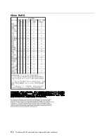
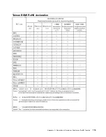
Page 128: ...B T 2 6572 A 0 1 B C 2 3 4 D E 6 1 7 8 F G GB T 2 6572 H I J 3 4 L M N O P Q R S T U V W X Y Z 0 1 _3 a b cd4 efgh ij kl cd4 mnop qrs op tu v wvs xys zI cd4 n ij cd4 mech W mech s 34 01 114 ThinkServer RS160 User Guide and Hardware Maintenance Manual ...

Page 129: ...Taiwan BSMI RoHS declaration Appendix C Restriction of Hazardous Substances RoHS Directive 115 ...

Page 130: ...116 ThinkServer RS160 User Guide and Hardware Maintenance Manual ...

Page 131: ... program functionality Particulate contamination Attention Airborne particulates including metal flakes or particles and reactive gases acting alone or in combination with other environmental factors such as humidity or temperature might pose a risk to the server that is described in this document Risks that are posed by the presence of excessive particulate levels or concentrations of harmful gas...

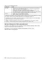
Page 132: ...leaning Devices for Removal Efficiency by Particle Size Atlanta American Society of Heating Refrigerating and Air Conditioning Engineers Inc 2 The deliquescent relative humidity of particulate contamination is the relative humidity at which the dust absorbs enough water to become wet and promote ionic conduction 3 ANSI ISA 71 04 1985 Environmental conditions for process measurement and control sys...

Page 133: ...e publication Lenovo may make improvements and or changes in the product s and or the program s described in this publication at any time without notice The products described in this document are not intended for use in implantation or other life support applications where malfunction may result in injury or death to persons The information contained in this document does not affect or change Len...

Page 134: ...on are trademarks of Intel Corporation or its subsidiaries in the U S and or other countries Internet Explorer Microsoft and Windows are trademarks of the Microsoft group of companies Linux is a registered trademark of Linus Torvalds Other company product or service names may be trademarks or service marks of others 120 ThinkServer RS160 User Guide and Hardware Maintenance Manual ...

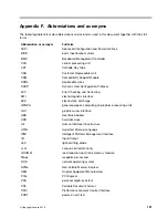
Page 135: ...MI electromagnetic interface ESD electrostatic discharge GPGPU general purpose computing on graphics processing units GUI graphical user interface HBA Host Bus Adapter HDD hard disk drive HII Human Interface Infrastructure HTML Hypertext Markup Language IPMI Intelligent Platform Management Interface I O Input Output LED light emitting diode LLW Lenovo Limited Warranty LRDIMM load reduction dual in...

Page 136: ...ATA Serial Advanced Technology Attachment SCCM System Center Configurations Management SD Secure digital SEL system event log SMI system management interrupt SSD solid state drive StorCLI Storage Command Line Tool TCG Trusted Computing Group TMM ThinkServer Management Module TPM ThinkServer Trusted Platform Module UEFI Unified Extensible Firmware Interface UPS uninterruptible power supply VGA vide...

Page 137: ...installation rules 53 remove 54 documentation using 101 E Ethernet controllers configuring 43 Ethernet status LED 14 Exit menu Setup Utility program 31 exiting Setup Utility program 34 export classification notice 105 F features 7 ThinkServer EasyStartup program 35 flashing the BIOS 34 front panel LED 12 locations 12 front panel board Installing 84 removing 84 front view of the server locations 11...

Page 138: ...y module install 55 installation rules 53 remove 54 memory module installation guidelines 53 microprocessor 89 N Network status LED 14 O Operating environment 10 optical drive install 62 installing 61 remove 61 removing 61 option completing the replacement 95 P particulate contamination 117 parts replacement completing 95 password considerations 32 setting changing deleting 32 Setup Utility progra...

Page 139: ...am 29 ThinkServer EasyStartup program 36 startup device selecting 33 Setup Utility program 33 static sensitive devices guidelines 46 static sensitive devices handling 46 system board 25 replacing 92 system board components locations 25 system event log troubleshooting and diagnostics 97 system fan installing 79 removing 78 system identification ID LED 15 system reliability guidelines 46 T Taiwan B...

Page 140: ... 118 U updating recovering 34 the BIOS 34 USB connector 15 using documentation 101 passwords 32 Setup Utility program 29 ThinkServer EasyStartup program 35 126 ThinkServer RS160 User Guide and Hardware Maintenance Manual ...

Page 141: ......

Page 142: ......

Reviews: