background image

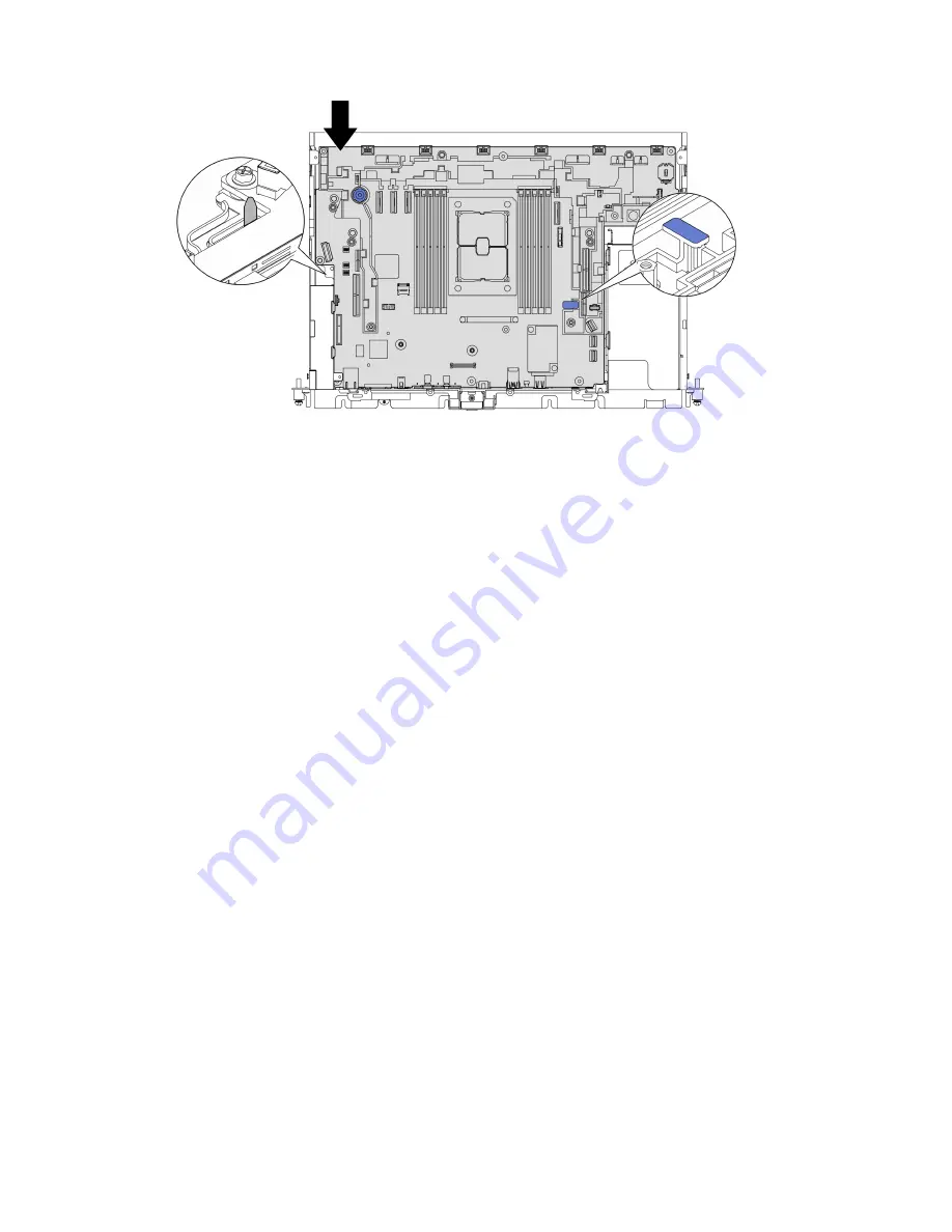
Figure 151. Securing the system board

After this task is completed

Proceed to 

“Update the machine type and serial number” on page 153

.

Update the machine type and serial number

After the system board is replaced by trained service technicians, the machine type and serial number must 

be updated.

There are two methods available to update the machine type and serial number: 

•  From Lenovo XClarity Provisioning Manager

To update the machine type and serial number from Lenovo XClarity Provisioning Manager: 

1.  Start the server and press the key according to the on-screen instructions to display the Lenovo 

XClarity Provisioning Manager interface. 

2.  If the power-on Administrator password is required, enter the password.
3.  From the System Summary page, click 

Update VPD

.

4.  Update the machine type and serial number.

•  From Lenovo XClarity Essentials OneCLI

Lenovo XClarity Essentials OneCLI sets the machine type and serial number in the Lenovo XClarity 
Controller. Select one of the following methods to access the Lenovo XClarity Controller and set the 
machine type and serial number: 

–  Operate from the target system, such as LAN or keyboard console style (KCS) access
–  Remote access to the target system (TCP/IP based)

To update the machine type and serial number from Lenovo XClarity Essentials OneCLI: 

1.  Download and install Lenovo XClarity Essentials OneCLI.

To download Lenovo XClarity Essentials OneCLI, go to the following site:

https://datacentersupport.lenovo.com/solutions/HT116433

Chapter 3

.

Hardware replacement procedures

153

Summary of Contents for 7D8T

Page 1: ...ThinkEdge SE450 Maintenance Manual Machine Types 7D8T ...

Page 2: ...ddition be sure that you are familiar with the terms and conditions of the Lenovo warranty for your server which can be found at http datacentersupport lenovo com warrantylookup Second Edition May 2022 Copyright Lenovo 2022 2022 LIMITED AND RESTRICTED RIGHTS NOTICE If data or software is delivered pursuant to a General Services Administration GSA contract use reproduction or disclosure is subject ...

Page 3: ... fan cage 70 Install the fan cage and the fans 73 Intrusion switch with cable replacement 77 Remove the intrusion switch with cable 77 Install the intrusion switch with cable 79 Heat sink Torx T30 nut replacement 82 Remove a heat sink Torx T30 nut 82 Install a heat sink Torx T30 nut 83 Memory module replacement 84 Remove a memory module 84 Install a memory module 87 M 2 boot adapter and drive repl...

Page 4: ...4 Complete the parts replacement 174 Hardware disassembling for chassis recycle 175 Chapter 4 Problem determination 177 Event logs 177 The front operator panel and error LEDs 179 System board LEDs 180 General problem determination procedures 180 Resolving suspected power problems 181 Resolving suspected Ethernet controller problems 181 Troubleshooting by symptom 182 Power on and power off problems...

Page 5: ...ligheidsvoorschriften Ennen kuin asennat tämän tuotteen lue turvaohjeet kohdasta Safety Information Avant d installer ce produit lisez les consignes de sécurité Vor der Installation dieses Produkts die Sicherheitshinweise lesen Prima di installare questo prodotto leggere le Informazioni sulla Sicurezza Les sikkerhetsinformasjonen Safety Information før du installerer dette produktet Antes de insta...

Page 6: ...Technology Lenovo assumes you are qualified in the servicing of equipment and trained in recognizing hazards energy levels in products Access to the equipment is by the use of a tool lock and key or other means of security and is controlled by the authority responsible for the location Important Electrical grounding of the server is required for operator safety and correct system function Proper g...

Page 7: ... or worn 3 Check for any obvious non Lenovo alterations Use good judgment as to the safety of any non Lenovo alterations 4 Check inside the server for any obvious unsafe conditions such as metal filings contamination water or other liquid or signs of fire or smoke damage 5 Check for worn frayed or pinched cables 6 Make sure that the power supply cover fasteners screws or rivets have not been remov...

Page 8: ...vi ThinkEdge SE450 Maintenance Manual ...

Page 9: ... and rugged it is designed for the non datacenter environment ideal for remote locations such as retail manufacturing and factory locations Figure 1 Product_name The server comes with a limited warranty For details about the warranty see https support lenovo com us en solutions ht503310 For details about your specific warranty see http datacentersupport lenovo com warrantylookup Specifications The...

Page 10: ...hes 444 6 mm 17 50 inches With rack latches 480 5 mm 18 92 inches Weight Varies with configuration Maximum 300mm chassis 14 84 kg 32 71 lbs 360mm chassis 17 45 kg 38 47 lbs Processor Varies with configuration Supports multi core Intel Xeon processors with integrated memory controller and Intel Mesh UPI Ultra Path Interconnect topology One processor socket Designed for LGA 4189 sockets Scalable up ...

Page 11: ...M 512 GB 3DS RDIMM 1024 GB PMEM RDIMM in Memory Mode 1280 GB For a list of supported memory modules see https serverproven lenovoapp com server se450 Storage expansion Two SATA M 2 drives Trayless drives two 15mm trayless SATA NVMe1 drives Drive 0 1 or four 7mm trayless SATA NVMe1 drives Drive 0 1 2 3 Hot swap optional 2 two 2 5 inch SATA NVMe drive bays with front access Drive 4 5 1 Only non SED ...

Page 12: ...t 1 GB speed Two universal serial bus USB 3 1 ports on the front Fans Six 60 mm x 60 mm x 56 mm trayless system fans with N 1 redundancy support Operating System Supported and certified operating systems include Microsoft Windows Server VMware ESXi Red Hat Enterprise Linux SUSE Linux Enterprise Server References Complete list of available operating systems https lenovopress com osig OS deployment ...

Page 13: ...ting 47 1 dBA Minimal 47 1 dBA Typical 59 4 dBA GPU rich Notes These sound levels were measured in controlled acoustical environments according to procedures specified by ISO7779 and are reported in accordance with ISO 9296 The declared acoustic sound levels are based on the following configurations which may change depending on configuration conditions Minimal 300mm Chassis 1x 185W 32cores CPU 8x...

Page 14: ...ent storage 40 C to 70 C 40 F to 158 F Maximum altitude 3 000 m 10 000 ft Relative Humidity non condensing Operating ASHRAE Class A2 8 to 80 maximum dew point 21 C 70 F ASHRAE Class A3 8 to 85 maximum dew point 24 C 75 F ASHRAE Class A4 8 to 90 maximum dew point 24 C 75 F NEBS Level 3 5 85 RH Non condensing Particulate contamination Attention Airborne particulates and reactive gases acting alone o...

Page 15: ...sive particulate levels or concentrations of harmful gases include damage that might cause the device to malfunction or cease functioning altogether This specification sets forth limits for particulates and gases that are intended to avoid such damage The limits must not be viewed or used as definitive limits because numerous other factors such as temperature or moisture content of the air can inf...

Page 16: ...earch Triangle Park North Carolina U S A 2 The derivation of the equivalence between the rate of copper corrosion growth in the thickness of the corrosion product in Å month and the rate of weight gain assumes that Cu2S and Cu2O grow in equal proportions 3 The derivation of the equivalence between the rate of silver corrosion growth in the thickness of the corrosion product in Å month and the rate...

Page 17: ...et update The installation or update is initiated from a computing device interacting directly with the server s Lenovo XClarity Controller UpdateXpress System Packs UXSPs UXSPs are bundled updates designed and tested to provide the interdependent level of functionality performance and compatibility UXSPs are server machine type specific and are built with firmware and device driver updates to sup...

Page 18: ...e the UEFI firmware and the Lenovo XClarity Provisioning Manager software Note By default the Lenovo XClarity Provisioning Manager Graphical User Interface is displayed when you start the server and press the key specified in the on screen instructions If you have changed that default to be the text based system setup you can bring up the Graphical User Interface from the text based system setup i...

Page 19: ...te can be performed within the host operating system of the server in band or remotely through the BMC of the server out of band For additional information about using Lenovo XClarity Essentials OneCLI to update firmware see http sysmgt lenovofiles com help topic toolsctr_cli_lenovo onecli_c_update html Lenovo XClarity Essentials UpdateXpress Lenovo XClarity Essentials UpdateXpress provides most o...

Page 20: ...from the navigation pane 3 Click Documentation Type Solution from the drop down menu Follow the on screen instructions to choose the category for the problem that you are having Security advisories Lenovo is committed to developing products and services that adhere to the highest security standards in order to protect our customers and their data When potential vulnerabilities are reported it is t...

Page 21: ...ntroller can place the server in a standby state as an automatic response to a critical system failure Start an orderly shutdown using the operating system if supported by your operating system Press the power button to start an orderly shutdown if supported by your operating system Press and hold the power button for more than 4 seconds to force a shutdown When in a standby state the server can r...

Page 22: ...14 ThinkEdge SE450 Maintenance Manual ...

Page 23: ...e machine type model and serial number FCC ID and IC Certification information The FCC and IC Certification information is identified by a label located on the edge server as shown in the following illustration Figure 2 Location of the ID label and FCC ID IC label Table 4 ID label and FCC ID IC label 1 ID label machine type and model information 2 FCC ID and IC Certification label Network access t...

Page 24: ...ile access to service information You can scan the QR code with a mobile device using a QR code reader application and get quick access to the Service Information web page The Service Information web page provides additional information for parts installation and replacement videos and error codes for server support Figure 4 SE450 QR code 16 ThinkEdge SE450 Maintenance Manual ...

Page 25: ... supply LEDs on page 18 11 VGA connector on page 19 5 Threaded studs for grounding on page 18 12 XClarity Controller XCC network connector on page 19 6 USB 2 0 with Lenovo XClarity Controller management on page 18 13 OCP 3 0 adapter on page 19 PCIe Slot 7 7 NMI button on page 18 1 Riser 1 PCIe slot 5 and 6 Supports the following Single width PCI Express 4 0 x16 x8 Slot 5 6 Single width PCI Express...

Page 26: ...to these lugs 6 USB 2 0 with Lenovo XClarity Controller management Connection to XClarity Controller is primarily intended for users with a mobile device running the XClarity Controller mobile application When a mobile device is connected to this USB port an Ethernet over USB connection is established between the mobile application running on the device and the XClarity Controller Select Network i...

Page 27: ... contains power controls indicator LEDs Figure 6 Front operator panel Table 6 Front operator panel controls and indicators 1 Reserved 4 Identification button LED blue on page 19 2 Power button LED green on page 19 5 System error LED yellow on page 20 3 Network activity LED green on page 19 2 Power button LED green Press this button to turn the server on and off manually The states of the power LED...

Page 28: ...on page 20 External LCD diagnostics handset The external LCD diagnostics handset is an external device that is connected to the server with a cable and it allows quick access to system information such as errors system status firmware network and health information Location of the external LCD diagnostics handset Location Callouts The external LCD diagnostics handset is connected to the server wit...

Page 29: ...o locate and select system information 3 Select button Press the select button to select from the options in the menu Option flow diagram The external LCD diagnostics handset displays various system information Navigate through the options with the scroll keys Depending on the model the options and entries on the LCD display might be different Chapter 2 Server components 21 ...

Page 30: ...een an option and the subordinate information entries with the select button and switch among options or information entries with the scroll buttons Depending on the model the options and entries on the LCD display might be different 22 ThinkEdge SE450 Maintenance Manual ...

Page 31: ...he Active Alerts menu will not be available during navigation 1 Active Alerts Details screen Error message ID Type Error Warning Information Occurrence time Possible sources of the error Active Alerts 1 Press to view alert details FQXSPPU009N Error 04 07 2020 02 37 39 PM CPU 1 Status Configuration Error System VPD Information Sub Menu Example Machine type and serial number Universal Unique ID UUID...

Page 32: ...ion number Release date XCC Backup Active Build D8BT05I Version 1 00 Date 2019 12 30 XCC Network Information Sub Menu Example XCC hostname MAC address IPv4 Network Mask IPv4 DNS IPv6 Link Local IP Stateless IPv6 IP Static IPv6 IP Current IPv6 Gateway IPv6 DNS Note Only the MAC address that is currently in use is displayed extension or shared XCC Network Information XCC Hostname XCC xxxx SN MAC Add...

Page 33: ... of active sessions Active User Sessions 1 Actions Sub Menu Example Several quick actions are available Restore XCC to Defaults Force XCC Reset Request XCC Reset Set UEFI Memory Test Clear CMOS Request Virtual Reseat Modify XCC Static IPv4 Address Net mask Gateway Modify System Name Generate Download FFDC Service Data Request XCC Reset This will request the BMC to reboot itself Hold for 3 seconds ...

Page 34: ...gure 7 Top view 300mm Table 7 Top view 300mm 1 Fan cage and fans 1 to 6 5 Riser 2 2 Intrusion switch 6 Riser 1 3 Power backplane 7 Air baffle for 300mm chassis 4 Power supply units 26 ThinkEdge SE450 Maintenance Manual ...

Page 35: ...ns 1 to 6 5 Riser 2 2 Intrusion switch 6 Riser 1 3 Power backplane 7 Air baffle for 360mm chassis 4 Power supply units 8 Supporting bracket System LEDs There are three sets of system LEDs on this server for various scenario See this topic for details Chapter 2 Server components 27 ...

Page 36: ...ge 28 9 Network activity LED green on page 29 14 Identification LED blue on page 29 4 Identification LED blue on page 29 10 Identification button LED blue on page 29 15 System error LED yellow on page 28 5 Network activity LED green on page 29 11 System error LED yellow on page 28 16 Reserved 6 Power LED green on page 29 17 Reserved 3 11 14 System error LED yellow When this yellow LED is lit it in...

Page 37: ...ver is transmitting to or receiving signals from the Ethernet LAN 6 8 12 Power button LED green Press this button to turn the server on and off manually Following are the states of the LED Off No power supply unit is properly installed or connected or the LED itself has failed Flashing rapidly four times per second The server is turned off and not ready to be turned on yet The power button is disa...

Page 38: ...rd LEDs Table 10 System board LEDs 1 DIMM error LED 10 to 6 5 ME heartbeat LED 2 Processor error LED 6 XCC heartbeat LED 3 DIMM error LED 5 to 1 7 FPGA heartbeat LED 4 System error LED 30 ThinkEdge SE450 Maintenance Manual ...

Page 39: ...Identifying connectors See this topic to locate and identify the connectors on the electric boards Chapter 2 Server components 31 ...

Page 40: ...sor socket 5 GPU power connector 1 18 DIMM slot 6 to 10 6 Intrusion switch connector 19 Serial port module connector 7 Power backplane side band connector 20 Reserved 8 Power backplane power connector 21 Top cover Wall mount LED cable connector 9 PCIe connector 2 22 PCIe connector 6 Riser 1 10 CMOS battery 3V CR3032 slots 23 OCP 3 0 Ethernet adapter connector 11 PCIe connector 1 Riser 2 24 PCIe co...

Page 41: ... Power backplane sideband connector 2 Power LED green 1 3 Power switch 4 Power supply unit 2 connector 5 Power supply unit 1 connector 1 When power LED is lit it means there server is powered on PCIe riser card connectors See this topic to locate the connectors on the PCIe riser cards Riser 1 Slot 5 to 6 Figure 13 Riser 1 connectors Chapter 2 Server components 33 ...

Page 42: ...lot 3 to 4 Figure 14 Riser 2 connectors Table 14 Riser 2 connectors 1 Riser card connector 1 Right angle 3 PCIe 4 0 x8 x16 Slot 4 2 PCIe 4 0 x8 x16 Slot 3 4 Riser card connector 0 Vertical Drive backplane connectors See this topic to locate the connectors on the drive backplane Figure 15 AnyBay drive backplane connectors 34 ThinkEdge SE450 Maintenance Manual ...

Page 43: ... the system board Table 16 System board switches Switches block Switch number Switch name Usage description On Off SW5 1 Machine Engine ME firmware security override ME update mode Normal default SW1 1 XClarity Controller boot backup The node will boot by using a backup of the XClarity Controller firmware Normal default 2 XClarity Controller force update Enables XClarity Controller force update No...

Page 44: ...splay compatible Note Depending on the model your server might look slightly different from the illustration The parts listed in the following table are identified as one of the following Tier 1 customer replaceable unit CRU Replacement of Tier 1 CRUs is your responsibility If Lenovo installs a Tier 1 CRU at your request with no service agreement you will be charged for the installation Tier 2 cus...

Page 45: ...Server components Figure 17 Server components Chapter 2 Server components 37 ...

Page 46: ... 1 Top cover 2 Top cover key 3 Heat sink 4 Heat sink Torx T30 nut 5 Processor 6 Persistent Memory Module PMEM 7 DRAM DIMM 8 CMOS battery CR3032 9 System board 10 Air baffle 300mm chassis 11 Heat sink filler 300mm chassis 12 Fan cover 300mm chassis 13 300mm chassis 14 GPU filler 360mm chassis 15 Air baffle 360mm chassis 16 Heat sink filler 300mm chassis 17 Fan cover 360mm chassis 18 Support bracket...

Page 47: ...m trayless drives 38 2 5 inch hot swap drives 39 Security bezel cable module filler 40 Security bezel cable module 41 EIA bracket left 42 EIA bracket right 43 7mm 15mm trayless drive cage 44 Fan cage 45 Fan 46 Full length double width PCIe adapter 47 Half length half width PCIe adapter 48 Firmware and TPM 2 0 Security Module 49 Serial port module 50 OCP 3 0 Ethernet adapter filler 51 OCP 3 0 Ether...

Page 48: ...andards Association CSA For units intended to be operated at 115 volts Use a UL listed and CSA certified cord set consisting of a minimum 18 AWG Type SVT or SJT three conductor cord a maximum of 15 feet in length and a parallel blade grounding type attachment plug rated 15 amperes 125 volts For units intended to be operated at 230 volts U S use Use a UL listed and CSA certified cord set consisting...

Page 49: ...lines are available as well Handling static sensitive devices on page 43 and Working inside the server with the power on on page 43 Make sure the components you are installing are supported by your server For a list of supported optional components for the server see https serverproven lenovo com server se450 When you install a new server download and apply the latest firmware This will help ensur...

Page 50: ...he drive while the server is still running Note See the system specific instructions for removing or installing a hot swap drive for any additional procedures that you might need to perform before you remove or install the drive After finishing working on the server make sure you reinstall all safety shields guards labels and ground wires System reliability guidelines Review the system reliability...

Page 51: ...ystem halt and loss of data by keeping static sensitive components in their static protective packages until installation and handling these devices with an electrostatic discharge wrist strap or other grounding system Limit your movement to prevent building up static electricity around you Take additional care when handling devices during cold weather for heating would reduce indoor humidity and ...

Page 52: ...procedure is available from the following link https www youtube com playlist list PLYV5R7hVcs DV_Ja2E7l6T lwN_IrnJRk Procedure Step 1 Make preparations for this task 1 If applicable remove the security bezel see Remove the security bezel on page 137 2 Remove the top covers see Remove the top covers on page 168 Step 2 Proceed to the topic corresponding to the server configuration Remove the air ba...

Page 53: ...pters Step 1 Remove the one captive screw and two thumbscrews that secure the supporting bracket to the chassis Figure 19 Releasing the air baffle assembly Step 2 Lift the air baffle along with the supporting bracket to remove the air baffle assembly Chapter 3 Hardware replacement procedures 45 ...

Page 54: ... length adapters Step 1 Remove the supporting bracket Figure 21 Removing the supporting bracket Loosen the one captive screw and two thumbscrews that secure the bracket to the chassis Loosen the other three screws and remove the bracket from the air baffle 46 ThinkEdge SE450 Maintenance Manual ...

Page 55: ...ve the fans and the fan cage on page 70 Figure 22 Cable routing for GPU power cables Table 18 Cable routing for GPU power cables From To 1 GPU in Slot 5 Riser 1 GPU power connector 2 2 GPU in Slot 4 Riser 2 GPU power connector 1 Step 3 Loosen the four captive screws then lift and remove both PCIe riser assemblies Chapter 3 Hardware replacement procedures 47 ...

Page 56: ...fle with full length adapters After this task is completed Make sure to install the air baffle back after finishing component replacement Attention Air baffle is required for the airflow that creates proper cooling Make sure to install the proper air baffle corresponding to the system configuration before power is turned on 48 ThinkEdge SE450 Maintenance Manual ...

Page 57: ...300mm chassis on page 49 Install the air baffle for 360mm chassis with half length adapters on page 51 Install the air baffle for 360mm chassis with full length adapters on page 54 Install the air baffle for 300mm chassis Procedure Step 1 Make sure the air baffle configuration fits the present system configuration Attention Fillers corresponding to system configuration are required for the airflow...

Page 58: ...r If the heat sink is 2U make sure the heat sink filler is removed from the air baffle Figure 26 Installing heat sink filler Press the release latch on the filler Remove the filler from the air baffle 50 ThinkEdge SE450 Maintenance Manual ...

Page 59: ...e sure the air baffle configuration fits the present system configuration Attention Fillers corresponding to system configuration are required for the airflow that does expected cooling Make sure to install the proper fillers corresponding to the system configuration 1 Heat sink filler If the heat sink is 1U make sure the heat sink filler is installed to the air baffle Chapter 3 Hardware replaceme...

Page 60: ...g heat sink filler If the heat sink is 2U make sure the heat sink filler is removed from the air baffle Figure 29 Installing the heat sink filler Press the release latch on the filler 52 ThinkEdge SE450 Maintenance Manual ...

Page 61: ...o the air baffle Figure 30 Installing the GPU fillers 3 Supporting bracket The supporting bracket is required in a 360mm chassis Secure it to the air baffle with the three captive screws as illustrated Figure 31 Securing the supporting bracket to the air baffle Step 2 Lower the air baffle into the chassis and press on it to ensure it is firmly seated Chapter 3 Hardware replacement procedures 53 ...

Page 62: ...igure 33 Securing the air baffle assembly Install the air baffle for 360mm chassis with full length adapters Procedure Step 1 Make sure the air baffle configuration fits the present system configuration 1 Heat sink filler If the heat sink is 1U make sure the heat sink filler is installed to the air baffle 54 ThinkEdge SE450 Maintenance Manual ...

Page 63: ...at sink filler If the heat sink is 2U make sure the heat sink filler is removed from the air baffle Figure 35 Installing the heat sink filler Press the release latch on the filler Chapter 3 Hardware replacement procedures 55 ...

Page 64: ...alled Loosen the three captive screws to remove the supporting bracket from the air baffle Figure 36 Removing the supporting bracket from the air baffle 3 GPU fillers GPU fillers must be removed when full length adapters s are to be installed If GPU fillers are installed in the air baffle remove them 56 ThinkEdge SE450 Maintenance Manual ...

Page 65: ... the air baffle Pinch on the retaining feet of the GPU fillers Remove the GPU fillers from the air baffle Step 2 Lower the air baffle into the chassis and press on it to ensure it is firmly seated Chapter 3 Hardware replacement procedures 57 ...

Page 66: ...nd install the CMOS batteries Remove the CMOS batteries CR2032 See this topic to learn how to remove the CMOS batteries About this task To avoid potential danger make sure to read the following safety information S002 CAUTION The power control button on the device and the power switch on the power supply do not turn off the electrical current supplied to the device The device also might have more ...

Page 67: ... properly to avoid potential danger Make sure to follow instructions in this topic while replacing the battery The CMOS battery must be replaced with another unit of the same type CR2032 For high temperature operation environment it is recommended to use CR2032HR instead After replacement is completed it is required to reconfigure the server and reset the system date and time Dispose of the batter...

Page 68: ...old the retaining latch then pivot the battery toward the positive side to disengage and remove it from the seat Figure 40 Removing the system battery After this task is completed Install a replacement unit see Install the CMOS battery CR2032 on page 60 Dispose the component with compliance to local regulations Install the CMOS battery CR2032 See this topic to learn how to install the CMOS battery...

Page 69: ... 100 C 212 F Repair or disassemble Dispose of the battery as required by local ordinances or regulations Consider the following when replacing the battery Remove the CMOS battery will cause system lockdown To unlock the system contact Lenovo Support Lenovo has designed this product with user safety in mind The lithium battery must be handled properly to avoid potential danger Make sure to follow i...

Page 70: ...reserved 2 System battery Install the system battery Procedure Step 1 Touch the static protective package that contains the component to any unpainted metal surface on the server then remove it from the package and place it on a static protective surface Step 2 Align the CMOS battery with the base of the seat with positive side faces middle of the chassis Then pivot the top of the battery until th...

Page 71: ...k with safety Turn off the server and peripheral devices and disconnect the power cords and all external cables see Power off the server on page 13 If the server is installed in a rack slide the server out on its rack slide rails to gain access to the top cover or remove the server from the rack Watch the procedure A video of this procedure is available from the following link https www youtube co...

Page 72: ...Figure 43 EIA bracket regular depth Figure 44 EIA bracket maximal depth 64 ThinkEdge SE450 Maintenance Manual ...

Page 73: ...ww youtube com playlist list PLYV5R7hVcs DV_Ja2E7l6T lwN_IrnJRk Procedure Step 1 Secure each of the EIA brackets to the chassis with six screws See the following for configuration specific details Regular depth Note Make sure to align the two brackets to the same numbers 1 to 6 on both sides of the chassis Figure 45 Regular depth mark 1 to 6 Chapter 3 Hardware replacement procedures 65 ...

Page 74: ...Figure 46 EIA bracket regular depth Maximal depth Note Make sure to remove the two pieces of mylar from each side of the chassis first 66 ThinkEdge SE450 Maintenance Manual ...

Page 75: ...Figure 47 Remove the mylar Figure 48 EIA bracket maximal depth Chapter 3 Hardware replacement procedures 67 ...

Page 76: ... link https www youtube com playlist list PLYV5R7hVcs DV_Ja2E7l6T lwN_IrnJRk Step 1 Disconnect the external LCD diagnostics handset cable Figure 49 Disconnecting the external LCD diagnostics handset cable Press and hold on the latch on top of the connector Pull and disconnect the cable from the server Install the external LCD diagnostics handset See this topic to learn how to install the external ...

Page 77: ...igure 50 Connecting the external LCD diagnostics handset cable Step 2 Attach the external LCD diagnostics handset to a metal surface with the magnetic bottom Chapter 3 Hardware replacement procedures 69 ...

Page 78: ...cage Remove the fans and the fan cage See this topic to learn how to remove the fans and the fan cage About this task S002 CAUTION The power control button on the device and the power switch on the power supply do not turn off the electrical current supplied to the device The device also might have more than one power cord To remove all electrical current from the device ensure that all power cord...

Page 79: ...ve the server from the rack Watch the procedure A video of this procedure is available from the following link https www youtube com playlist list PLYV5R7hVcs DV_Ja2E7l6T lwN_IrnJRk Procedure Step 1 Make preparations for this task 1 If applicable remove the security bezel see Remove the security bezel on page 137 2 Remove the top covers see Remove the top covers on page 168 3 Remove the air baffle...

Page 80: ...blue touch points on the top of the fan Lift the fan to remove it Remove the fan cage assembly Step 1 Loosen the two captive screws on the sides of the fan cage assembly and lift it to remove it from the chassis 72 ThinkEdge SE450 Maintenance Manual ...

Page 81: ...d the fans See this topic to learn how to install the fan cage and the fans About this task S002 CAUTION The power control button on the device and the power switch on the power supply do not turn off the electrical current supplied to the device The device also might have more than one power cord To remove all electrical current from the device ensure that all power cords are disconnected from th...

Page 82: ...c corresponding to the installation scenario Install a fan on page 74 Install the fan cage on page 74 Install a fan Step 1 Align a fan over the fan slot in the fan cage and insert the fan into the fan slot until it clicks into place Repeat this procedure until all the fans are installed in the fan cage Figure 54 Installing a fan Install the fan cage Step 1 Before installing the fan cage make sure ...

Page 83: ...ts on the top of the fan Lift the fan to remove it Step 2 Align the fan cage to the guides on both sides of the chassis and lower it into the chassis Then tighten the captive screws to secure the fan cage to the chassis Chapter 3 Hardware replacement procedures 75 ...

Page 84: ...lign a fan over the fan slot in the fan cage and insert the fan into the fan slot until it clicks into place Repeat this procedure until all the fans are installed in the fan cage Figure 57 Installing a fan 76 ThinkEdge SE450 Maintenance Manual ...

Page 85: ...installed in a rack slide the server out on its rack slide rails to gain access to the top cover or remove the server from the rack Watch the procedure A video of this procedure is available from the following link https www youtube com playlist list PLYV5R7hVcs DV_Ja2E7l6T lwN_IrnJRk Procedure Step 1 Make preparations for this task 1 If applicable remove the security bezel see Remove the security...

Page 86: ... the intrusion switch From To 1 Intrusion switch cable Intrusion switch Intrusion switch connector 2 Power backplane sideband cable Power backplane Power backplane sideband connector Step 3 Remove the screw that secures the intrusion switch and pull the intrusion switch up to remove it 78 ThinkEdge SE450 Maintenance Manual ...

Page 87: ...r shipping that are supplied to you Install the intrusion switch with cable See this topic to learn how to install the intrusion switch with cable About this task Watch the procedure A video of this procedure is available from the following link https www youtube com playlist list PLYV5R7hVcs DV_Ja2E7l6T lwN_IrnJRk Procedure Step 1 Make sure the power backplane sideband cable is disengaged from th...

Page 88: ... switch From To 1 Intrusion switch cable Intrusion switch Intrusion switch connector 2 Power backplane sideband cable Power backplane Power backplane sideband connector Step 2 Align the intrusion switch with the guide slot and shoulder pin on the chassis then secure the intrusion switch with a screw 80 ThinkEdge SE450 Maintenance Manual ...

Page 89: ...n switch with cable through the cable clip and connect it to the connector on the system board Step 4 Secure the power backplane sideband cable in the cable clip Figure 62 Cable routing for the power backplane and the intrusion switch Chapter 3 Hardware replacement procedures 81 ...

Page 90: ... off the server on page 13 If the server is installed in a rack slide the server out on its rack slide rails to gain access to the top cover or remove the server from the rack Do not touch the processor contacts Contaminants on the processor contacts such as oil from your skin can cause connection failures Note The heat sink processor and processor carrier for the system might be different from th...

Page 91: ...nk Torx T30 nut on page 83 If you are instructed to return the component or optional device follow all packaging instructions and use any packaging materials for shipping that are supplied to you Install a heat sink Torx T30 nut See this topic to learn how to install a PEEK Polyether ether ketone Torx T30 nut on the heat sink About this task Note The heat sink processor and processor carrier for t...

Page 92: ...30 nut is secured under the four clips in the socket After this task is completed 1 Make sure all four nuts are installed to the PHM and install the PHM See Install a processor and heat sink on page 133 2 Proceed to complete the parts replacement see Complete the parts replacement on page 174 Memory module replacement See these topics to learn how to remove and install a DIMM Remove a memory modul...

Page 93: ...server out on its rack slide rails to gain access to the top cover or remove the server from the rack Watch the procedure A video of this procedure is available from the following link https www youtube com playlist list PLYV5R7hVcs DV_Ja2E7l6T lwN_IrnJRk Procedure Step 1 Make preparations for this task 1 If any of the modules to be removed is PMEM In the case of pure system board or expansion tra...

Page 94: ...ions HT508642 e Reboot the system 2 If applicable remove the security bezel see Remove the security bezel on page 137 3 Remove the top covers see Remove the top covers on page 168 4 Remove the air baffle see Remove the air baffle on page 43 5 Locate the memory module to be removed on the system board and remove the corresponding components Figure 65 Memory module slots on the system board To remov...

Page 95: ...tructions and use any packaging materials for shipping that are supplied to you Install a memory module See this topic to learn how to install a memory module About this task See Memory module installation rules and order in Setup Guide for detailed information about memory configuration and setup ATTENTION Static Sensitive Device Ground package before opening on page 43 Attention Memory modules a...

Page 96: ... any of the modules to be installed is PMEM make sure to complete the following procedure before physically installing the module 1 Back up stored data in PMEM namespaces 2 Disable PMEM security with one of the following options LXPM Go to UEFI Setup System Settings Intel Optane PMEMs Security Press to Disable Security and input passphrase to disable security Setup Utility Go to System Configurati...

Page 97: ...memory module Figure 68 Installing a memory module Open the retaining clip Align the memory module with the slot Firmly press both ends of the memory module straight down until the retaining clip snaps into the locked position Chapter 3 Hardware replacement procedures 89 ...

Page 98: ... About this task Attention Go over Installation Guidelines on page 41 to ensure that you work with safety Turn off the server and peripheral devices and disconnect the power cords and all external cables see Power off the server on page 13 If the server is installed in a rack slide the server out on its rack slide rails to gain access to the top cover or remove the server from the rack Watch the p...

Page 99: ...on the retainer clip Slightly push the retainer clip left to disengage the M 2 drives Pivot the rear side of the M 2 drives away from the backplane Remove the M 2 drives After this task is completed Install replacement units of M 2 drives see Install the M 2 drives and boot adapter on page 92 Chapter 3 Hardware replacement procedures 91 ...

Page 100: ...osen the captive screw that secure the M 2 cable to the adapter Disconnect the M 2 cable from the adapter Open the cover on the adapter Loosen the captive screw that secure the M 2 backplane to the adapter Remove the screw that secure the M 2 backplane to the adapter Remove the M 2 backplane from the adapter Install the M 2 drives and boot adapter See this topic to learn how to install the M 2 dri...

Page 101: ...replacement backplane to the adapter Figure 72 Installing the M 2 backplane Align the backplane with the slot in the adapter Tighten the captive screw on the M 2 backplane Secure the M 2 backplane with a screw Close the adapter cover Connect the M 2 cable to the backplane Tighten the captive screw to secure the M 2 cable Step 2 Install the M 2 drives to the backplane Chapter 3 Hardware replacement...

Page 102: ...d the two cable clips as illustrated Align the pointed ends of the two triangles on the adapter and the power supply cage and lower the bracket Then slide the adapter backward slightly and tighten the captive screw to secure the adapter Note To spare space for proper installation make sure to contain the cables with the two cable clips as illustrated before installing the adapter Figure 74 Install...

Page 103: ...and all external cables see Power off the server on page 13 If the server is installed in a rack slide the server out on its rack slide rails to gain access to the top cover or remove the server from the rack Watch the procedure A video of this procedure is available from the following link https www youtube com playlist list PLYV5R7hVcs DV_Ja2E7l6T lwN_IrnJRk Procedure Step 1 Make preparations fo...

Page 104: ...follow all packaging instructions and use any packaging materials for shipping that are supplied to you If you plan to recycle the OCP adapter complete the following steps 1 Loosen the two captive screws that secure the cover to the adapter and remove the cover Figure 76 Disassembling the OCP adapter 2 Separate the adapter from the lower cover 96 ThinkEdge SE450 Maintenance Manual ...

Page 105: ...Riser 1 adapter configuration is x16 or x16 x8 so that PCIe 4 and 5 slots on the system board are available for the OCP cable Watch the procedure A video of this procedure is available from the following link https www youtube com playlist list PLYV5R7hVcs DV_Ja2E7l6T lwN_IrnJRk Procedure Step 1 If the OCP cable has not been installed complete the following steps a If necessary remove the screw th...

Page 106: ...plicable see Remove the PCIe riser assemblies and adapters on page 100 c Align the pointed ends of two triangles on the OCP cable and OCP cage and secure the cable with two screws Figure 79 Installing the OCP cable d Connect the OCP cable to the system board Make sure to contain the cable with the clip as illustrated 98 ThinkEdge SE450 Maintenance Manual ...

Page 107: ...onnector Step 2 Slide the OCP Ethernet adapter into the chassis and tighten the captive screw to secure the adapter Figure 81 Installing the OCP Ethernet adapter Step 3 Connect Ethernet cables to the OCP Ethernet adapter After this task is completed Proceed to complete the parts replacement see Complete the parts replacement on page 174 Chapter 3 Hardware replacement procedures 99 ...

Page 108: ...1 If applicable remove the security bezel see Remove the security bezel on page 137 2 Remove the top covers see Remove the top covers on page 168 3 Remove the air baffle see Remove the air baffle on page 43 Step 2 Proceed to the corresponding topic to the type of PCIe riser assembly to be removed Riser assemblies with half length adapters Riser assembly with AnyBay drive cage on page 102 Riser ass...

Page 109: ...r 2 Step 3 Open the retainer and remove the screws that secure the adapter to the riser Figure 84 Removing the retaining screws Step 4 Press on the latch to disengage the adapter from the riser and remove the adapter Chapter 3 Hardware replacement procedures 101 ...

Page 110: ...AnyBay drive cage Step 2 Loosen the two captive screws then lift the riser assembly to remove it from the chassis Figure 86 Removing PCIe riser 2 with drive cage Step 3 Gently rotate the release latch away to unlock the drive handle then grasp and pull the handle to remove the drive from the drive bay 102 ThinkEdge SE450 Maintenance Manual ...

Page 111: ...captive screw and two thumbscrews that secure the bracket to the chassis Loosen the other three screws and remove the bracket from the air baffle Step 2 Disconnect the GPU power cables from the adapters Note If there is a plan of replacing GPU power cables make sure to remove the fan cage first see Remove the fans and the fan cage on page 70 Chapter 3 Hardware replacement procedures 103 ...

Page 112: ...connector 2 2 GPU in Slot 4 Riser 2 GPU power connector 1 Step 3 Loosen the four captive screws then lift and remove both PCIe riser assemblies Figure 90 Removing PCIe riser assemblies with full length adapters Step 4 Open the retainer and remove the screws that secure the adapter to the riser 104 ThinkEdge SE450 Maintenance Manual ...

Page 113: ... 5 Press on the latch to disengage the adapter from the riser and remove the adapter Figure 92 Removing an adapter from the riser Step 6 If necessary lift the air baffle and remove it from the chassis Chapter 3 Hardware replacement procedures 105 ...

Page 114: ...e follow all packaging instructions and use any packaging materials for shipping that are supplied to you If there is a recycle plan complete the following step corresponding to the component to be recycled Remove the PCIe riser card from the riser Riser 1 Remove the three screws that secure the riser card to the riser 106 ThinkEdge SE450 Maintenance Manual ...

Page 115: ...Figure 94 Disassembling Riser 1 Riser 2 Remove the four screws that secure the riser card to the riser Chapter 3 Hardware replacement procedures 107 ...

Page 116: ... riser cage Figure 96 Disassembling the AnyBay drive cage Install the PCIe adapters and riser assemblies See this topic to learn how to install the PCIe adapters and riser assemblies About this task 1 Before installing the PCIe riser assemblies make sure to complete installation and cable routing of trayless drives and the drive cage 108 ThinkEdge SE450 Maintenance Manual ...

Page 117: ...er card connector 0 Vertical RISER2 0 RISER2 0 3 Proceed to the corresponding topic to the type of PCIe adapters to be installed Install half length adapters and riser assemblies on page 109 Install PCIe Riser 2 with AnyBay drive cage on page 112 Install full length adapters and riser assemblies 360mm chassis on page 114 Watch the procedure A video of this procedure is available from the following...

Page 118: ...Figure 97 Installing the riser card to Riser 1 Riser 2 Secure the riser card to the riser with four screws 110 ThinkEdge SE450 Maintenance Manual ...

Page 119: ... the riser assembly and push it in until the latch clicks in the lock position Figure 99 Installing an adapter to the riser Step 3 Secure the adapter with screws and close the retaining latch Two spared screws are available on the side of the riser Chapter 3 Hardware replacement procedures 111 ...

Page 120: ...at the same procedure on the other riser assembly If the other riser is Riser 2 with AnyBay drive cage proceed to Install PCIe Riser 2 with AnyBay drive cage on page 112 Step 6 Reconnect the cables if applicable Note x16 x16 configuration does not require riser cables Install PCIe Riser 2 with AnyBay drive cage Procedure Step 1 If necessary secure the AnyBay drive backplane to the riser cage with ...

Page 121: ...ve handle then slide the drive into the drive bay until it stops and rotate the handle back to the locked position Figure 104 Installing the hot swap drives Step 3 Lower the riser assembly until it is firmly seated then tighten the two captive screws to secure it to the chassis Chapter 3 Hardware replacement procedures 113 ...

Page 122: ...econnect the cables if applicable Install full length adapters and riser assemblies 360mm chassis Procedure Step 1 If necessary install the PCIe riser card to the riser Riser 1 Secure the riser card to the riser with three screws 114 ThinkEdge SE450 Maintenance Manual ...

Page 123: ...Figure 106 Installing the riser card to Riser 1 Riser 2 Secure the riser card to the riser with four screws Chapter 3 Hardware replacement procedures 115 ...

Page 124: ...re connected to the system board Step 3 Make sure the air baffle is installed before installing the PCIe riser assemblies Figure 108 Installing the air baffle Notes If the heat sink is 1U make sure the heat sink filler is installed to the air baffle 116 ThinkEdge SE450 Maintenance Manual ...

Page 125: ...he riser assembly and push it in until the latch clicks in the lock position Figure 110 Installing an adapter to the riser Step 5 Secure the adapter with screws and close the retaining latch Two spared screws are available on the side of the riser Chapter 3 Hardware replacement procedures 117 ...

Page 126: ...cabled to the adapters Step 7 Lower the riser assembly until it is firmly seated then tighten the two captive screws to secure it to the chassis Figure 112 Installing the riser assemblies Step 8 Route the GPU power cables as illustrated 118 ThinkEdge SE450 Maintenance Manual ...

Page 127: ... to secure the power cables along the channel on the air baffle Table 25 Cable routing for GPU power cables From To 1 GPU in Slot 5 Riser 1 GPU power connector 2 2 GPU in Slot 4 Riser 2 GPU power connector 1 Step 9 Install the supporting bracket Chapter 3 Hardware replacement procedures 119 ...

Page 128: ...power backplane See this topic to learn how to remove the power backplane About this task Attention Go over Installation Guidelines on page 41 to ensure that you work with safety Turn off the server and peripheral devices and disconnect the power cords and all external cables see Power off the server on page 13 If the server is installed in a rack slide the server out on its rack slide rails to ga...

Page 129: ...from the power backplane Step 3 Hold and lift the power backplane to remove it from the chassis Figure 115 Removing the power backplane After this task is completed Install a replacement unit see Install the power backplane on page 121 If you are instructed to return the component or optional device follow all packaging instructions and use any packaging materials for shipping that are supplied to...

Page 130: ...s firmly seated Figure 116 Installing the power backplane Step 2 Connect the power side band cable to the power backplane Step 3 Secure the power backplane sideband cable to the cable clip Figure 117 Cable routing for the power backplane and the intrusion switch 122 ThinkEdge SE450 Maintenance Manual ...

Page 131: ...ower LED green 2 Power switch Step 5 If available Hook the front end of the switch cap to the power backplane and rotate the other end to secure the cap then apply the label to the power backplane Figure 118 Applying the switch cap and label After this task is completed Proceed to complete the parts replacement see Complete the parts replacement on page 174 Power supply replacement See these topic...

Page 132: ...e that all power cords are disconnected from the power source S009 CAUTION To avoid personal injury disconnect the fan cables before removing the fan from the device S035 CAUTION Never remove the cover on a power supply or any part that has this label attached Hazardous voltage current and energy levels are present inside any component that has this label attached There are no serviceable parts in...

Page 133: ...for shipping that are supplied to you Install a hot swap power supply unit See this topic to learn how to install a hot swap power supply unit About this task To avoid potential danger make sure to read the following safety information S002 CAUTION The power control button on the device and the power switch on the power supply do not turn off the electrical current supplied to the device The devic...

Page 134: ...ou suspect a problem with one of these parts contact a service technician Watch the procedure A video of this procedure is available from the following link https www youtube com playlist list PLYV5R7hVcs DV_Ja2E7l6T lwN_IrnJRk Procedure Step 1 Grasp the handle on the power supply unit and slide it into the power supply bay until it clicks into place Figure 120 Installing a hot swap power supply u...

Page 135: ...u work safely Power off the server and disconnect all power cords for this task Prevent exposure to static electricity which might lead to system halt and loss of data by keeping static sensitive components in their static protective packages until installation and handling these devices with an electrostatic discharge wrist strap or other grounding system If the server is in a rack remove it from...

Page 136: ... 27 Processor locations 1 Processor Note The heat sink processor and processor carrier for your system might be different from those shown in the illustrations The following illustration shows the components of the PHM 128 ThinkEdge SE450 Maintenance Manual ...

Page 137: ...eat sink Watch the procedure A video of this procedure is available from the following link https www youtube com playlist list PLYV5R7hVcs DV_Ja2E7l6T lwN_IrnJRk Procedure Step 1 Make preparations for this task 1 If applicable remove the security bezel see Remove the security bezel on page 137 2 Remove the top covers see Remove the top covers on page 168 3 Remove the air baffle see Remove the air...

Page 138: ...rotect empty processor sockets immediately with a cover If you are removing the PHM as part of a system board replacement set the PHM aside If you are reusing the processor or heat sink separate the processor from its retainer See Separate the processor from carrier and heat sink on page 130 If you are instructed to return the defective component please package the part to prevent any shipping dam...

Page 139: ...ith any surface can compromise the thermal grease rendering it ineffective Thermal grease can damage components such as the electrical connectors in the processor socket Note The heat sink processor and processor carrier for your system might be different than those shown in the illustrations Watch the procedure A video of this procedure is available from the following link https www youtube com p...

Page 140: ...e heat sink Lift the carrier from the heat sink Wipe the thermal grease from the bottom of the heat sink with an alcohol cleaning pad After this task is completed If you are instructed to return the component or optional device follow all packaging instructions and use any packaging materials for shipping that are supplied to you 132 ThinkEdge SE450 Maintenance Manual ...

Page 141: ...tallation and handling these devices with an electrostatic discharge wrist strap or other grounding system Each processor socket must always contain a cover or a PHM When removing or installing a PHM protect empty processor sockets with a cover Do not touch the processor socket or processor contacts Processor socket contacts are very fragile and easily damaged Contaminants on the processor contact...

Page 142: ... install a new PHM or replacement processor update your system firmware to the latest level See Update the firmware in the ThinkEdge SE450 Setup Guide The following illustration shows the components of the PHM Figure 127 PHM components 1 Heat sink 9 Clips to secure processor in carrier 2 Heat sink triangular mark 10 Carrier triangular mark 3 Processor identification label 11 Processor ejector hand...

Page 143: ...k Note If you are unable to remove the label and place it on the new heat sink or if the label is damaged during transfer write the processor serial number from the processor identification label on the new heat sink in the same location as the label would be placed using a permanent marker b Install the processor into a new carrier Note Replacement heat sinks come with both gray and black process...

Page 144: ...ular mark on the carrier is aligned with the triangular mark in the shipping tray b If there is any old thermal grease on the processor gently wipe the top of the processor with an alcohol cleaning pad Note Make sure the alcohol has fully evaporated before applying new thermal grease c Apply the thermal grease on the top of the processor with syringe by forming four uniformly spaced dots while eac...

Page 145: ...utward until they engage with the hooks in the socket Fully tighten the Torx T30 nuts in the installation sequence shown on the heat sink label Tighten the screws until they stop then visually inspect to make sure that there is no gap between the screw shoulder beneath the heat sink and the processor socket For reference the torque required for the fasteners to fully tighten is 1 1 newton meters 1...

Page 146: ...server out on its rack slide rails to gain access to the top cover or remove the server from the rack Watch the procedure A video of this procedure is available from the following link https www youtube com playlist list PLYV5R7hVcs DV_Ja2E7l6T lwN_IrnJRk Procedure Step 1 Unlock the security bezel with the corresponding key It is stored at the location as illustrated Figure 132 Security bezel key ...

Page 147: ...y Turn off the server and peripheral devices and disconnect the power cords and all external cables see Power off the server on page 13 If the server is installed in a rack slide the server out on its rack slide rails to gain access to the top cover or remove the server from the rack Watch the procedure A video of this procedure is available from the following link https www youtube com playlist l...

Page 148: ...component or optional device follow all packaging instructions and use any packaging materials for shipping that are supplied to you Install the dust filter See this topic to learn how to install the dust filter About this task Watch the procedure A video of this procedure is available from the following link https www youtube com playlist list PLYV5R7hVcs DV_Ja2E7l6T lwN_IrnJRk Procedure Step 1 I...

Page 149: ... to install the security bezel and the dust filter About this task Watch the procedure A video of this procedure is available from the following link https www youtube com playlist list PLYV5R7hVcs DV_Ja2E7l6T lwN_IrnJRk Procedure Attention When installing the security bezel for the first time Make sure the security cable module is installed If not install it see Install the security bezel cable m...

Page 150: ...lots on the chassis and insert the bezel hooks in the slots on both sides Figure 137 Installing the security bezel Step 2 Lock the security bezel with the key After this task is completed Proceed to complete the parts replacement see Complete the parts replacement on page 174 142 ThinkEdge SE450 Maintenance Manual ...

Page 151: ... and disconnect the power cords and all external cables see Power off the server on page 13 If the server is installed in a rack slide the server out on its rack slide rails to gain access to the top cover or remove the server from the rack Watch the procedure A video of this procedure is available from the following link https www youtube com playlist list PLYV5R7hVcs DV_Ja2E7l6T lwN_IrnJRk Proce...

Page 152: ... security bezel cable module Operation of this task must be done by trained technicians that are certified by Lenovo Service About this task Watch the procedure A video of this procedure is available from the following link https www youtube com playlist list PLYV5R7hVcs DV_Ja2E7l6T lwN_IrnJRk Procedure Step 1 Secure the security bezel cable module with three screws as illustrated Attention Removi...

Page 153: ... module See this topic to learn how to remove the serial port module About this task Attention Go over Installation Guidelines on page 41 to ensure that you work with safety Turn off the server and peripheral devices and disconnect the power cords and all external cables see Power off the server on page 13 If the server is installed in a rack slide the server out on its rack slide rails to gain ac...

Page 154: ...curity bezel on page 137 2 Remove the top covers see Remove the top covers on page 168 3 Remove the air baffle see Remove the air baffle on page 43 4 Remove PCIe riser 1 see Remove the PCIe riser assemblies and adapters on page 100 Step 2 Disconnect the serial port cable from the system board Figure 140 Disconnecting the serial port cable Step 3 Open the retainer and remove the screws that secures...

Page 155: ... all packaging instructions and use any packaging materials for shipping that are supplied to you Install the serial port module See this topic to learn how to install the serial port module About this task Note This module can only be installed to PCIe Slot 6 in Riser 1 Watch the procedure A video of this procedure is available from the following link https www youtube com playlist list PLYV5R7hV...

Page 156: ...ort module to the riser Step 2 Secure the module to the riser with a screw and close the retainer Figure 144 Securing the serial port module Step 3 Connect the serial port cable to the system board 148 ThinkEdge SE450 Maintenance Manual ...

Page 157: ...his task Attention Removing and installing this component requires trained technicians that are certified by Lenovo Service Do no attempt to remove or install it without proper training and qualification Go over Installation Guidelines on page 41 to ensure that you work with safety Turn off the server and peripheral devices and disconnect the power cords and all external cables see Power off the s...

Page 158: ... a hot swap power supply unit on page 124 9 Remove the power backplane see Remove the power backplane on page 120 10 Remove the intrusion switch cable see Remove the intrusion switch with cable on page 77 11 Remove all the memory modules see Remove a memory module on page 84 12 Remove the Root of Trust Module see Remove the Firmware and TPM 2 0 Security Module on page 166 13 Remove the processor a...

Page 159: ...of recycle remove the screws as marked in the following illustration and separate the supporting sheet from the system board Figure 148 Recycling the system board Install the system board assembly See this topic to learn how to install the system board assembly This procedure must be executed by a trained technician Chapter 3 Hardware replacement procedures 151 ...

Page 160: ...ting pull tab removal Watch the procedure A video of this procedure is available from the following link https www youtube com playlist list PLYV5R7hVcs DV_Ja2E7l6T lwN_IrnJRk Procedure Step 1 Align the guide pin in the chassis with the slot on the left side of the system board and lower the right end into the chassis Figure 150 Installing the system board Step 2 Hold the handle and the rear edge ...

Page 161: ... Administrator password is required enter the password 3 From the System Summary page click Update VPD 4 Update the machine type and serial number From Lenovo XClarity Essentials OneCLI Lenovo XClarity Essentials OneCLI sets the machine type and serial number in the Lenovo XClarity Controller Select one of the following methods to access the Lenovo XClarity Controller and set the machine type and ...

Page 162: ... 12 accounts The default value is USERID xcc_password The BMC IMM XCC account password 1 of 12 accounts Example commands are as follows onecli config set SYSTEM_PROD_DATA SysInfoProdName m t_model bmc username xcc_user_id bmc password xcc_password onecli config set SYSTEM_PROD_DATA SysInfoSerialNum s n bmc username xcc_user_id bmc password xcc_password Online KCS access unauthenticated and user re...

Page 163: ...help topic lxpm_frontend lxpm_product_page html 2 If the power on Administrator password is required enter the password 3 From the UEFI Setup page click System Settings Security Secure Boot 4 Enable Secure Boot and save the settings From Lenovo XClarity Essentials OneCLI To enable UEFI Secure Boot from Lenovo XClarity Essentials OneCLI 1 Download and install Lenovo XClarity Essentials OneCLI To do...

Page 164: ...of this procedure is available from the following link https www youtube com playlist list PLYV5R7hVcs DV_Ja2E7l6T lwN_IrnJRk Procedure Step 1 Make preparations for this task 1 If applicable remove the security bezel see Remove the security bezel on page 137 2 Remove the top covers see Remove the top covers on page 168 3 Remove the air baffle see Remove the air baffle on page 43 4 Remove both PCIe...

Page 165: ...e the cover to the cage and remove the cover Figure 153 Removing the drive cage cover Step 4 To remove the drives from the drive cage proceed to the topic corresponding to the system configuration Remove the 7mm trayless drives on page 158 Remove the 15mm trayless drives on page 159 Chapter 3 Hardware replacement procedures 157 ...

Page 166: ...gure 154 Removing 7mm trayless drives Step 2 Remove the drive spacer Figure 155 Removing the drive spacer Note Make sure to keep the spacer for future use In the case that there is not immediate need of the spacer store it on the bottom of the drive cage 158 ThinkEdge SE450 Maintenance Manual ...

Page 167: ... lower drives out from the drive cage to remove them Figure 157 Removing 7mm trayless drives Remove the 15mm trayless drives Procedure Step 1 Slide the two drives out from the drive cage to remove them Chapter 3 Hardware replacement procedures 159 ...

Page 168: ...nstall the drive cage and trayless drives See this topic to learn how to install the drive cage and trayless drives About this task Start with the topic corresponding to the planned configuration Install the 7mm trayless drives on page 160 Install the 15mm trayless drives on page 163 Install the 7mm trayless drives Step 1 If the spacer is store on the bottom of the drive cage slide it left slightl...

Page 169: ...stalling screws and connecting drive cables Note 16 spared screws are kept on the drive cage as illustrated Figure 161 Spared screws on the drive cage Step 3 Align the screws on the two drives with the slots on the drive cage and slide the drives in until the screws are secured in the slots Chapter 3 Hardware replacement procedures 161 ...

Page 170: ...cer to the guiding pin in the drive cage and place the spacer on top of the two drives Figure 163 Placing the drive spacer Step 5 Align the screws on the two upper drives with the slots on the drive cage and lower the drives until the screws are secured in the slots 162 ThinkEdge SE450 Maintenance Manual ...

Page 171: ...e 164 Install the 15mm trayless drives Step 1 Install four screws on each of the drives and connect the cables to the drives according to the cable routing plan Figure 165 Installing screws and connecting drive cables Note 16 spared screws are kept on the drive cage as illustrated Chapter 3 Hardware replacement procedures 163 ...

Page 172: ...ews are secured in the slots Figure 167 Installing 15mm trayless drives Step 3 Proceed to install the drive cage see Install the drive cage on page 164 Install the drive cage Step 1 Align the captive screws on the cover with screw holes on the drive cage and tighten the captive screws to secure the cover to the cage 164 ThinkEdge SE450 Maintenance Manual ...

Page 173: ...gnal cables make sure to contain power cables first Figure 169 Routing cables through the drive cage cable clips 1 Signal cable 2 Power cable Step 3 Align the tabs on the drive cage with the guide pins on the chassis and lower the drive cage then tighten the two captive screws to secure the drive cage Chapter 3 Hardware replacement procedures 165 ...

Page 174: ...rtified by Lenovo Service Do no attempt to remove or install it without proper training and qualification Remove the Firmware and TPM 2 0 Security Module See this topic to learn how to remove the Firmware and TPM 2 0 Security Module About this task Attention Go over Installation Guidelines on page 41 to ensure that you work with safety Turn off the server and peripheral devices and disconnect the ...

Page 175: ...re the Firmware and TPM 2 0 Security Module to the system board and remove the module Figure 171 Removing the Firmware and TPM 2 0 Security Module After this task is completed Install a replacement unit see Install the Firmware and TPM 2 0 Security Module on page 167 If you are instructed to return the component or optional device follow all packaging instructions and use any packaging materials f...

Page 176: ...w to remove and install the top cover and the fan cover Remove the top covers See this topic to learn how to remove the top cover and the fan cover About this task Attention Go over Installation Guidelines on page 41 to ensure that you work with safety Turn off the server and peripheral devices and disconnect the power cords and all external cables see Power off the server on page 13 If the server...

Page 177: ... buttons to disengage the top cover Slide the top cover slightly backward and remove it Note If the two blue buttons cannot be pressed down try slide the cover forward and press the buttons again Step 2 Press on the release buttons on both sides and slid the fan cover slightly forward to remove it Figure 174 Remove the fan cover 300mm Chapter 3 Hardware replacement procedures 169 ...

Page 178: ... to you Install the top covers See this topic to learn how to install the top cover and the fan cover About this task Watch the procedure A video of this procedure is available from the following link https www youtube com playlist list PLYV5R7hVcs DV_Ja2E7l6T lwN_IrnJRk Procedure Step 1 Align the top cover with the guiding slots on both sides of the chassis and slide it forward slightly 170 Think...

Page 179: ...he top cover Step 2 Align the fan cover with the guiding slots on both sides of the chassis and slide it backwards slightly to secure it Figure 177 Installing the fan cover 300mm Chapter 3 Hardware replacement procedures 171 ...

Page 180: ...cement trained technician only See these topics to learn how to remove or install the wall mount LED cable Only trained technicians are allowed to do the replacement of this component Attention Removing and installing this component requires trained technicians that are certified by Lenovo Service Do no attempt to remove or install it without proper training and qualification Remove the wall mount...

Page 181: ... applicable remove the security bezel see Remove the security bezel on page 137 2 Remove the top covers see Remove the top covers on page 168 3 Remove the air baffle see Remove the air baffle on page 43 4 Remove PCIe riser 1 see Remove the PCIe riser assemblies and adapters on page 100 Step 2 Disconnect the cable from the system board then remove the two screws that secure it to the OCP cage and r...

Page 182: ...cable After this task is completed Proceed to complete the parts replacement see Complete the parts replacement on page 174 Complete the parts replacement Go through this checklist before completing parts replacement To complete parts replacement go through the following list 1 Ensure that all the removed components have been properly reinstalled and that no tools or loose screws are left inside y...

Page 183: ... bezel on page 137 Step 2 Remove the power supply units see Remove a hot swap power supply unit on page 124 Step 3 Remove the top covers see Remove the top covers on page 168 Step 4 Remove the air baffle see Remove the air baffle on page 43 Step 5 Remove the fan cage assembly see Remove the fan cage assembly on page 72 Step 6 Remove both PCIe riser assemblies see Remove the PCIe riser assemblies a...

Page 184: ...176 ThinkEdge SE450 Maintenance Manual ...

Page 185: ...using some other management application begin with the Lenovo XClarity Controller event log Event logs An alert is a message or other indication that signals an event or an impending event Alerts are generated by the Lenovo XClarity Controller or by UEFI in the servers These alerts are stored in the Lenovo XClarity Controller Event Log If the server is managed by the Chassis Management Module 2 or...

Page 186: ...nal physical variables such as temperature power supply voltages fan speeds and component status The Lenovo XClarity Controller provides various interfaces to systems management software and to system administrators and users to enable remote management and control of a server The Lenovo XClarity Controller monitors all components of the server and posts events in the Lenovo XClarity Controller ev...

Page 187: ...es per second The server is off and not ready to be turned on The power button is disabled in this status This will last approximately 5 to 10 seconds after power source is connected Flashing slowly once per second The server is off and ready to be turned on Press the power button to turn on the server On The server is turned on 3 Network activity LED green When this LED is blinking it indicates t...

Page 188: ...LED 3 DIMM error LED 5 to 1 7 FPGA heartbeat LED 4 System error LED General problem determination procedures Use the information in this section to resolve problems if the event log does not contain specific errors or the server is inoperative If you are not sure about the cause of a problem and the power supplies are working correctly complete the following steps to attempt to resolve the problem...

Page 189: ... loose screw is causing a short circuit on a circuit board Step 3 Remove the adapters and disconnect the cables and power cords to all internal and external devices until the server is at the minimum configuration that is required for the server to start See Specifications on page 1 to determine the minimum configuration for your server Step 4 Reconnect all ac power cords and turn on the server If...

Page 190: ...annot connect to the network but the hardware appears to be working the network administrator must investigate other possible causes of the error Troubleshooting by symptom See this topic to learn how to find solutions to problems that have identifiable symptoms To use the symptom based troubleshooting information in this section complete the following steps 1 Check the event log of the applicatio...

Page 191: ...ts c Check if any power supply error LED it lit see Power supply LEDs on page 18 and replace the faulty unit if any is found If the problem persists call Lenovo service The following steps are for Lenovo Service only 1 If there is readable system event log with uefi errors replace the Root of Trust Module see Firmware and TPM 2 0 Security Module replacement trained technician only on page 166 2 If...

Page 192: ...EDs persist to indicate PMEMs are installed in wrong slots on page 187 Cannot create goal successfully when installing PMEMs to the system for the first time on page 187 Multiple memory modules identified as failing or disabled Complete the following procedure to solve the problem 1 Check XCC log to see if one of the disabled modules is malfunctioning If so replace the malfunctioning module and st...

Page 193: ... of memory are enabled The server might have automatically disabled a memory bank when it detected a problem or a memory bank might have been manually disabled There is no memory mismatch when the server is at the minimum memory configuration If PMEMs are installed a Refer to PMEM rules in Setup Guide and see if the displayed memory fits the mode description b All the saved data have been backed u...

Page 194: ...namespaces and creates an extra new namespace during system booting Delete the created namespaces in either the Setup Utility or the operating system before the first booting with ESXi Migrated PMEMs are not supported If this warning message appears complete the following steps Intel Optane PMEM interleave set DIMM X is migrated from another system Platform ID 0x00 these migrated PMEMs are not sup...

Page 195: ...wrong slots AC the system or restart XCC to solve this problem Cannot create goal successfully when installing PMEMs to the system for the first time When seeing ones of the following messages ERROR Cannot retrieve memory resources info ERROR One or more PMEM modules do not have PCD data A platform reboot is recommended to restore valid PCD data Complete the following steps to solve the problem 1 ...

Page 196: ...adable rolling or distorted on page 189 The wrong characters appear on the screen on page 189 Management controller remote presence cannot work on page 189 Incorrect characters are displayed Complete the following steps 1 Verify that the language and locality settings are correct for the keyboard and operating system 2 If the wrong language is displayed update the server firmware to the latest lev...

Page 197: ... monitor cable 3 Replace the components listed in step 2 one at a time in the order shown restarting the server each time a Monitor cable b Video adapter if one is installed c Monitor d Trained technician only System board The wrong characters appear on the screen Complete the following steps until the problem is solved 1 Verify that the language and locality settings are correct for the keyboard ...

Page 198: ...the server then replace the KVM switch USB device does not work 1 Make sure that The correct USB device driver is installed The operating system supports USB devices 2 Make sure that the USB configuration options are set correctly in system setup Restart the server and press the key specified in the on screen instructions to display the Lenovo XClarity Provisioning Manager system setup interface T...

Page 199: ...is resolved 1 Press Enter to access System Setup Utility 2 Select System Settings Devices and I O Ports MM Config Base then modify the setting to increase the device resources For example modify 3 GB to 2 GB or modify 2 GB to 1 GB 3 Save the settings and restart the system 4 If the error recurs with the highest device resource setting 1GB shutdown the system and remove some PCIe devices then power...

Page 200: ...ess than the number of installed serial ports Complete the following steps until the problem is solved 1 Make sure that Each port is assigned a unique address in the Setup utility and none of the serial ports is disabled The serial port adapter if one is present is seated correctly 2 Reseat the serial port adapter 3 Replace the serial port adapter Serial device does not work 1 Make sure that The d...

Page 201: ...ard problems Make sure that all cables and the console breakout cable are properly connected and secure Mouse problems Make sure that all cables and the console breakout cable are properly connected and secure Intermittent unexpected reboots Note Some correctable errors require that the server reboot so that it can disable a device such as a memory DIMM or a processor to allow the machine to boot ...

Page 202: ...e is not too high see Specifications on page 1 c The air vents are not blocked d The air baffle is installed securely 2 Reseat the dual port network adapter 3 Turn off the server and disconnect it from the power source then wait 10 seconds before restarting the server 4 If the problem still remains replace the dual port network adapter Could not log in using LDAP account with SSL enabled Complete ...

Page 203: ...view processor details from system setup To determine if the processor is supported for the server see https serverproven lenovo com server se450 3 Trained technician only Make sure that processor 1 is seated correctly 4 Trained technician only Remove processor 2 and restart the server 5 Replace the following components one at a time in the order shown restarting the server each time a Trained tec...

Page 204: ...hat you can make the necessary corrections to the configuration and restart the server If the server is unable to successfully complete POST with the default configuration there might be a problem with the system board You can specify the number of consecutive restart attempts in System Setup Restart the server and press the key specified in the on screen instructions to display the Lenovo XClarit...

Page 205: ...upport Software problems See this topic to learn how to solve software problems 1 To determine whether the problem is caused by the software make sure that The server has the minimum memory that is needed to use the software For memory requirements see the information that comes with the software Note If you have just installed an adapter or memory the server might have a memory address conflict T...

Page 206: ...198 ThinkEdge SE450 Maintenance Manual ...

Page 207: ...system lenovofiles com help index jsp You can take these steps to try to solve the problem yourself Check all cables to make sure that they are connected Check the power switches to make sure that the system and any optional devices are turned on Check for updated software firmware and operating system device drivers for your Lenovo product The Lenovo Warranty terms and conditions state that you t...

Page 208: ...e Request Collecting service data To clearly identify the root cause of a server issue or at the request of Lenovo Support you might need collect service data that can be used for further analysis Service data includes information such as event logs and hardware inventory Service data can be collected through the following tools Lenovo XClarity Provisioning Manager Use the Collect Service Data fun...

Page 209: ...about the operating system such as the operating system event log in addition to the hardware service data To obtain service data you can run the getinfor command For more information about running the getinfor see http sysmgt lenovofiles com help topic toolsctr_cli_lenovo onecli_r_getinfor_command html Contacting Support You can contact Support to obtain help for your issue You can receive hardwa...

Page 210: ...202 ThinkEdge SE450 Maintenance Manual ...

Page 211: ...ew editions of the publication Lenovo may make improvements and or changes in the product s and or the program s described in this publication at any time without notice The products described in this document are not intended for use in implantation or other life support applications where malfunction may result in injury or death to persons The information contained in this document does not aff...

Page 212: ...drive bays with the largest currently supported drives that are available from Lenovo Maximum memory might require replacement of the standard memory with an optional memory module Each solid state memory cell has an intrinsic finite number of write cycles that the cell can incur Therefore a solid state device has a maximum number of write cycles that it can be subjected to expressed as total byte...

Page 213: ... that are supplied with the monitor Additional electronic emissions notices are available at http thinksystem lenovofiles com help index jsp Taiwan BSMI RoHS declaration Figure 186 Taiwan BSMI RoHS declaration Taiwan import and export contact information Contacts are available for Taiwan import and export information Manufacturer Appendix B Notices 205 ...

Page 214: ...USA company name Lenovo Global Technology United States Inc USA company address 7001 Development Dr Building 7 Morrisville NC 27560 USA 206 ThinkEdge SE450 Maintenance Manual ...

Page 215: ...0 intermittent problems 192 K keyboard problems 189 M memory problems 184 monitor problems 188 mouse problems 189 N network problems 194 notes important 204 notices 203 O observable problems 195 optional device problems 190 P particulate contamination 7 parts replacement completing 174 PCIe troubleshooting 190 power cords 40 power off the server 13 power on the server 12 power problems 181 problem...

Page 216: ...205 Tech Tips 12 telecommunication regulatory statement 204 telephone numbers 201 trademarks 204 troubleshooting 188 190 197 by symptom 182 DRAM 184 intermittent problems 192 keyboard problems 189 memory problems 184 mouse problems 189 network problems 194 observable problems 195 PMEM 184 power on and power off problems 182 serial device problems 192 symptoms based troubleshooting 182 USB device p...

Page 217: ......

Page 218: ......

Reviews: