15. EXTERNAL INTERFACE
180
15. EXTERNAL
INTERFACE
15.1
Remote Feature (Option)
The remote feature is a factory option (LV 5381 OP70; sold separately). By adding this option,
you can use the remote control connector on the rear panel to load presets, transmit alarm
signals, and perform other operations. Use the 15-pin D-sub connector that comes with the
option.
15.1.1
Remote Control Connector Specifications
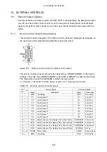
This section contains a diagram of the remote control connector, displayed as it appears on
the rear panel, and a table that describes the connector's pinout.
Figure 15-1 Remote control connector (female, inch screws)
The remote control connector pinout varies depending on REMOTE MODE in the system
settings. The mode when REMOTE MODE is set to BIT or BINARY is called normal mode.
The mode when it is set to COMMAND is called command mode.
For information on the REMOTE MODE setting, see section 5.5.1, “Selecting Remote Mode.”
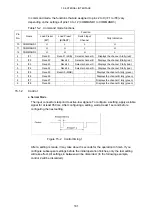
Table 15-1 Remote control connector pinout
Normal Mode
Command Mode
Pin
No.
I/O
Name Description
Name
Description
1 - GND Grounding
GND Grounding
2
I
/P1
Loads preset 1
/F1
Function 1
3
I
/P2
Loads preset 2
/F2
Function 2
4
I
/P3
Loads preset 3
/F3
Function 3
5
I
/P4
Loads preset 4
/F4
Function 4
6
I
/P5
Loads preset 5
/F5
Function 5
7
I
/P6
Loads preset 6
/F6
Function 6
8
I
/P7
Loads preset 7
/F7
Function 7
9
I
/P8
Loads preset 8
/F8
Function 8
10
I
/ACH
Selects channel A or displays the channel A tally
COMMAND1 Command 1
11
I
/BCH
Selects channel B or displays the channel B tally
COMMAND2 Command 2
12
I
/CCH
Selects channel C or displays the channel C tally
COMMAND3 Command 3
13
I
/DCH
Selects channel D or displays the channel D tally
/STROBE
Strobe
14
O
ALARM Alarm output
ALARM
Alarm output
15 - GND Grounding
GND Grounding

