background image

Safety 31

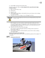
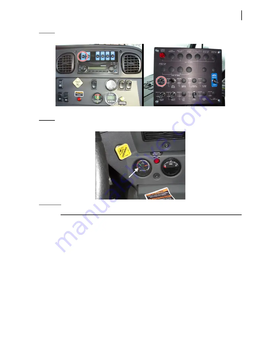
Figure 2-18      Hydraulic pump O

N

/O

FF

 switch on the dashboard (left), on the console (right)

Once the engine is started, wait for air pressure to build up to 

at least

 70

 psi.

Figure 2-19      Air pressure indicator

I

MPORTANT

:

Do not operate or move the vehicle until air pressure has reached 70

 psi.

Summary of Contents for 2R-III

Page 1: ...2R III MAINTENANCE MANUAL...

Page 2: ......

Page 3: ...2R III MAINTENANCE MANUAL...

Page 4: ...on contained in this document All risks and damages incidental or otherwise arising from the use or misuse of the information contained herein are entirely the responsibility of the user Although care...

Page 5: ......

Page 6: ......

Page 7: ...13 Employer Responsibilities 13 Employee Responsibilities 14 Things to Do 14 Things to Avoid 14 Safety Precautions 15 Prior to Start Up 15 General Operation 16 Hydraulics 18 Fire Protection 18 Houseke...

Page 8: ...eventive Maintenance 45 Operating and Maintenance Records 45 Lubrication Chart 46 Recommended Lubricants 46 Hydraulic System Service 47 Checking Fluid Level Daily 47 Checking Tank Breather Cap Weekly...

Page 9: ...Down to Interrupted Cycle Position 84 Packer Panel Sweeps Hopper 85 Packing Refuse 1 86 Packing Refuse 2 87 Raising Tailgate 88 Ejecting Load 89 Retracting Pushout Panel 90 Lowering Tailgate 91 Servic...

Page 10: ...escopic Cylinder 139 Pushout Panel 140 Wear Block Replacement 141 Removal of Pushout Panel 142 Installation of Pushout Panel 143 Carrier and Packer Panels 144 Packer Panel 145 Removal of Packer Panel...

Page 11: ...arbage truck Terms You Will Need to Know Body s main components are the hopper the packer panel the tailgate the pushout panel and the carrier panel During collection refuse is contained inside the bo...

Page 12: ...2 Introduction TERMS YOU WILL NEED TO KNOW TAILGATE ASSEMBLY BODY ASSEMBLY HOPPER LOADING EDGE HYDRAULIC TANK PUSHOUT PANEL CARRIER PANEL PACKER PANEL TERMS YOU WILL NEED TO KNOW...

Page 13: ...first loaded into the hopper of the tailgate assembly The carrier and packer panels which sweep up and pack the refuse from the hopper will be in the home position Packing When the operator starts the...

Page 14: ...sure is applied to the cylinders which control movement of the carrier and packer panels This causes the refuse to be compacted tightly allowing for a large carrying capacity Once the body is full the...

Page 15: ...nt required to lift and empty these containers will vary according to the container s type and size The following are some handling systems that could be used A hydraulically operated container push b...

Page 16: ...Opening 2 Back 3 Heel 4 Hook Safety Latch 5 Tip 6 Base ____________________________ Container 1 Trunnion Bar 2 Hook Attachment 3 Lid ____________________________ Container Attachment 1 Loading Sill 2...

Page 17: ...Lifting Cylinder CLC 1 Control Levers 2 Engine Speed Up Button 3 Cylinder Cable Roller Guide 4 Cylinder Cable 5 Lifting Cylinder Assembly 6 Container Attachment 7 Stop Bar Lid Guard __________________...

Page 18: ...loader by securing it with the latch arms of the container attachment Dumping A container handling system is used to raise the container and empty its content into the hopper of the rear loader Relea...

Page 19: ...te Marie Victorin Levis QC G7A 2T3 Toll Free 1 877 831 8250 Telephone 1 418 831 8250 Service Fax 1 418 831 1673 Parts Fax 1 418 831 7561 Parts and warranty During business hours 8 00 AM to 5 00 PM Eas...

Page 20: ...10 Introduction...

Page 21: ...n any way represent an all inclusive list It is the operators responsibility to be familiar with and ensure that operation is in accordance with safety requirements and codes including all applicable...

Page 22: ...G and CAUTION notations accompanied by an exclamation mark inside a triangle an International Hazard Symbol are used to alert the operator and mechanics to special instructions concerning a particular...

Page 23: ...ncial state and federal safety standards To keep the vehicle maintained and properly adjusted to meet the manufacturer s standards and recommendations For help or for more information please contact t...

Page 24: ...know where to get assistance in the event of an emergency IMPORTANT Do not use damaged equipment Things to Do Make sure that the area is clear of any people or possible obstructions IMPORTANT Be extr...

Page 25: ...ging Out the Vehicle on page 28 Proper servicing requires specialized tools and procedures Service must be performed by authorized personnel only following procedures in the 2R III Maintenance Manual...

Page 26: ...hill Never place head body fingers or any limbs into a scissors point or pinch point on the equipment Before operating the vehicle the driver must be thoroughly familiar with the employer s safety pr...

Page 27: ...een pickups or when parked This prevents inadvertent engine speed up if the tailgate carrier panel control lever is shifted The tailgate clamps must be tightened securely before starting to load Do no...

Page 28: ...the hopper compartment or try to repair anything on the packer when it is moving or when the hydraulic pump is still running Personnel authorized to get into the hopper must first lock out and tag out...

Page 29: ...riangle kit are provided with the truck Figure 2 2 5 lb fire extinguisher left optional 20 lb fire extinguisher right Housekeeping Good housekeeping habits are a major factor in accident prevention Ke...

Page 30: ...The tailgate safety props are located under the tailgate one on each side IMPORTANT Make sure that the body is empty before installing the safety props Setting the Tailgate Safety Props for units equ...

Page 31: ...6 Unlatch each prop from its stored position and swivel it towards the body see Figure 2 5 Figure 2 5 Props in stored position left and in service position right Danger Prior to raising the tailgate m...

Page 32: ...put the tailgate safety props back into their stored position 1 Start the engine 2 Turn the pump ON 3 Raise the tailgate by about 3 feet using the TAILGATE lever see Figure 2 4 4 Swivel back each safe...

Page 33: ...light indicator should turn off Figure 2 9 TAILGATE OPEN light indicator 6 Put the tailgate clamps back in place see Figure 2 3 To do so 6 a Swivel back the clamp against the body 6 b Tighten the cla...

Page 34: ...is unlocked both locking mechanism cylinders are retracted They are extended when the tailgate is locked Figure 2 11 Locking mechanism cylinder 5 Using the TAILGATE lever raise the tailgate about 3 f...

Page 35: ...y close the tailgate The TAILGATE OPEN light indicator should turn off see Figure 2 9 6 Using the tailgate latch button on the body left side corner near the access door see Figure 2 10 lock the tailg...

Page 36: ...rd tailgate clamps 1 Make sure that the body is empty 2 Remove both tailgate clamps see Figure 2 3 To do so 2 a Loosen the clamp 2 b Swing the clamp away from the body 3 Start the truck 4 Engage the p...

Page 37: ...on the console should turn on Check they are all working If for some reason any of these elements are not activated report this to your supervisor or maintenance personnel 6 Using the TAILGATE lever...

Page 38: ...if not repeat the adjustment procedure If after several attempts the switch does not work properly replace the faulty switch with a new one Locking Out and Tagging Out the Vehicle For any inspection r...

Page 39: ...device and or mechanism to make sure that there is no bypass and that they are all functional Shutting Down the Vehicle If the vehicle has to be stored for an extended period of time follow the chass...

Page 40: ...is fully open before starting the vehicle see Figure 2 17 Figure 2 17 Suction line shut off valve NOTE The hydraulic tank model may vary according to the options installed on the vehicle 3 Engage the...

Page 41: ...itch on the dashboard left on the console right Once the engine is started wait for air pressure to build up to at least 70 psi Figure 2 19 Air pressure indicator IMPORTANT Do not operate or move the...

Page 42: ...32 Safety...

Page 43: ...ifies their equipment must do so in accordance with American National Standards Institute Z245 1 1999 It is important to note that deviating from these procedures could cause damage to the unit or ren...

Page 44: ...tor Safety Precautions Prior to Performing any Service or Repair Before performing any service or repair the following tasks should be carried out Set the parking brake Put the vehicle in park or if e...

Page 45: ...lding should be done in a well ventilated area The radiation given off by the arc will destroy the retina of the eye Wear an approved welder s helmet Welding radiation will produce severe burns on unp...

Page 46: ...non flammable solvent before disassembly Inspect the component after cleaning for signs of wear or external damage When disassembling a component note the position of each part as it is removed to ai...

Page 47: ...e is present the light will be on If no voltage is present the light will be off Checking Continuity A continuity tester is used to check the ability of a conductor to allow current to pass A continui...

Page 48: ...on the anode side and the positive red lead on the cathode side The multimeter should read very high ohms of resistance k ohm or open range If the resistance is low the diode is damaged and must be r...

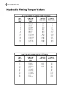
Page 49: ...78 55 7 61 70 9 68 20 55 7 61 78 10 79 1 2 13 75 10 37 85 11 76 105 14 52 20 85 11 76 120 16 60 9 16 12 110 15 21 120 16 60 155 21 44 18 120 16 60 170 23 51 5 8 11 150 20 75 167 23 10 210 29 04 18 170...

Page 50: ...TORQUE INCH LBS TORQUE FOOT LBS 2 5 16 24 35 2 3 3 8 24 65 5 4 7 16 20 130 11 5 1 2 20 165 14 6 9 16 18 235 20 8 3 4 16 525 43 10 7 8 14 650 55 12 1 1 16 12 950 80 14 1 3 16 12 1200 100 16 1 5 16 12 1...

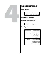
Page 51: ...rvice quality grade Fluid Tank 50 gallons System Pressure Settings 2350 PSI 162 BAR Type of Fittings Steel Tubing w Brazed Fittings Reinforced Rubber Hose w Crimped Full Flow ORFS Fittings O Ring Fitt...

Page 52: ...Type Positive Displacement Gear Type Driven by the PTO from the Truck Transmission or by the Engine Capacity 42 GPM 1200 RPM Grade ISO Viscosity 22 32 46 AGMA NO Gravity API Flash F Pour Point Viscos...

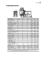
Page 53: ...opper Opening Height 56 56 56 1423mm 1423mm 1423mm T Hopper Inside Width 80 80 80 2032mm 2032mm 2032mm U Rear of Body to Rear of 74 74 74 1880mm 1880mm 1880mm Tailgate Closed Height Above Chassis Fram...

Page 54: ...in Leach hydraulic systems In addition to the above characteristics selected additives should be incorporated to provide additional resistance to wear corrosion oxidation decomposition and foaming All...

Page 55: ...o anticipate and prevent operational difficulties before they require extended shut down for costly repairs OperatingandMaintenance Records Prepare and adhere to a maintenance schedule Keep detailed r...

Page 56: ...rease may be used for all lube points except control levers Lubrication of the control levers on the tailgate must be done weekly every 40 hours of operation using lubricating oil SAE 10 or equivalent...

Page 57: ...maintenance of the hydraulic components is of vital importance to the service life of the system and the operation of the unit as a whole Checking Fluid Level Daily Place the carrier and packer panels...

Page 58: ...48 Preventive Maintenance Figure 5 1 Hydraulic tank w return filter 1 2 3 4 5 6 7 8...

Page 59: ...Filter Element To replace the filter element 1 Remove filter cover see Figure 5 1 4 2 Remove o ring see Figure 5 1 5 3 Remove element see Figure 5 1 6 and discard 4 Install a new element see Figure 5...

Page 60: ...of time It is also essential that moisture and water be kept from the hydraulic fluids and system Daily Preventive Maintenance Each day perform the following maintenance Inspection Perform the pre ope...

Page 61: ...arms will not latch securely in the assembly do not use the unit A visual inspection of the wire rope cable should identify any broken wires or obvious damage A visual inspection of the chains should...

Page 62: ...eck out procedures listed in Chapter 6 of this manual Container Handling System Hardware Check the container handling system hardware to make sure that no damage exists and that all fasteners are secu...

Page 63: ...tion and secure end connections Damage or deterioration requiring replacement of wire rope is indicated by broken wires excessive wear heat damage corrosion stretching or distortion as shown in the wi...

Page 64: ...um of every forty 40 hours of operation Monthly Preventive Maintenance Lifting Hook A thorough inspection of any container lifting hook should be completed once a month consisting of checking for dist...

Page 65: ...l the hydraulic tank as described in Flushing Hydraulic System Cleaning Hydraulic Strainer Yearly on page 49 Once a year remove clean and inspect the suction strainer as described in Flushing Hydrauli...

Page 66: ...56 Preventive Maintenance...

Page 67: ...he location of various controls some checks will require two people Warning Make sure you know and observe all safety precautions listed in Chapter 2 before performing any of the following check out p...

Page 68: ...e pushout cylinder in the retract position The fluid level should be between the safe range marks on the sight gauge If not 4 Add hydraulic fluid for normal operating and weather conditions See Hydrau...

Page 69: ...System section on page 156 Checking Engine Speed Up Switches Body To check engine speed up switches located on the body 1 Depress the engine speed up push button The engine should speed up OPERATIONAL...

Page 70: ...the wiring or switch and repair See Electrical System on page 156 Checking Pack Cycle Time To check pack cycle time 1 Activate both the packer panel lever and carrier panel lever Using a stopwatch ti...

Page 71: ...ecking Pressures The pressure checks provided below will indicate the operating condition of the hydraulic system Detailed adjustment procedures are provided later in this section and are referenced a...

Page 72: ...ailgate clamps 2 Depress speed up button 3 Move tailgate control lever to fully raise the tailgate 4 Hold lever and read gauge OPERATIONAL STATUS Truck Running PTO Engaged Speed Up On Transmission Neu...

Page 73: ...cartridge and turn the adjusting screw in rotate clockwise to reach the correct pressure If the pressure is above the appropriate setting loosen the lock nut on the relief cartridge and turn the adjus...

Page 74: ...as described in Checking Main Line Pressure on page 62 2 Reduce main relief setting to below 1000 PSI 69 BAR 3 Using a screwdriver remove the button plugs from the end of the Main Control Valve packe...

Page 75: ...sting screw located inside the bonnet clockwise to increase the knockout pressure setting or counter clockwise to decrease the pressure setting Once the proper knockout setting has been attained reins...

Page 76: ...Out Figure 6 2 Hydraulic gauge 2 Install LabriePlus part HYF13701 plug see above illustration on the hydraulic hose connected to the extension side of the cylinder 3 Install hydraulic connectors as sh...

Page 77: ...PSI on the gauge If pressure stops going up before reaching that value tighten the pressure set screw by a quarter of a turn and repeat pumping operation Repeat this step until pressure has reached 1...

Page 78: ...shown on illustration OPERATIONAL STATUS Truck Off PTO Disengaged Attachport a power with 0 6000 psi gauge to port marked P2 When the adjusted pressure is reached 3800 psi fluid will drain from port m...

Page 79: ...n on illustration OPERATIONAL STATUS Truck Off PTO Disengaged Attachport a power with 0 3000 psi gauge to port marked P2 When the adjusted pressure is reached 1700 psi fluid will drain from port marke...

Page 80: ...re there is metal to metal contact Shim or replace worn parts as described in Pushout Panel on page 140 Power Take Off P T O Periodically re torque the mounting bolts or studs as outlined in the P T O...

Page 81: ...ining which parts are associated with a particular function Problems in the hydraulic system may be found by performing the PRESSURE CHECKS found in Chapter 6 Compaction Before troubleshooting a unit...

Page 82: ...s that result from dieseling in the hydraulic system are small in size and many may be needed to eventually damage a piston seal to the extent that bypass will occur Where does the air come from The a...

Page 83: ...tems and ensure that all inlet connections are tight and not ingesting air Troubleshooting Tables Use the following troubleshooting tables to find remedies to problems that have identifiable signs OPE...

Page 84: ...r replace and or balance all parts Pump gears end plates bearings etc badly worn Replace pump Improper grade of hydraulic fluid fluid foaming Replace with proper grade of hydraulic fluid see Leach Hyd...

Page 85: ...rrier panel lever speed up switch is defective Repair replace or adjust as required PACKER PANEL VALVE SECTION SHIFTS TOO SLOW Possible cause Remedy Object in hopper that the packer panel cannot move...

Page 86: ...Knockout Pressures on page 64 Linkage binding or restrictive Inspect and free linkage as necessary PACKER CARRIER PANELS DO NOT DELIVER FULL FORCE TO PACK LOAD INTO BODY Possible cause Remedy Hydrauli...

Page 87: ...Valve Release speed up button Only partially pull feather the Front Control Valve control handle LOAD WILL NOT PUSH OUT Possible cause Remedy Less than full pressure in telescopic cylinder Perform te...

Page 88: ...TS OPEN WHILE PACKING LOAD INTO BODY Possible cause Remedy Packer panel cylinder seal leaking Perform test for leaking cylinder See Chapter 8 Service and Repair Packer panel valve section shift pressu...

Page 89: ...ssure see Checking Main Line Pressure on page 62 Hydraulic pump is defective Replace pump See Hydraulic Pump on page 152 Main relief cartridge out of adjustment or broken Adjust or replace main relief...

Page 90: ...y or pin WINCH MOTOR LEAKING Possible cause Remedy Shaft seal damaged Replace shaft seal Motor worn internally Replace motor CONTAINER RAISES VERY SLOWLY Possible cause Remedy Winch motor by passing R...

Page 91: ...ion of the hydraulic flow and the interaction of system components i e valves and cylinders follows Before proceeding to the flow diagram refer to the illustration on next page and become familiar wit...

Page 92: ...es through the valve to and through the MCV Main Control Valve and then back to the tank During packer operation if pressure increases to the main relief setting excess flow will be diverted from the...

Page 93: ...ft diverting flow to the rod end of the packer panel cylinders The packer panel cylinders retract causing the packer panel to sweep rearward over the load Return fluid flow from the cylinder is back t...

Page 94: ...tract moving the carrier and packer panels down to the interrupted cycle position trapped fluid keeps the packer panel cylinders retracted At the end of the carrier cylinder retraction stroke pressure...

Page 95: ...anel cylinders As the cylinders extend the packer panel sweeps the load forward in the hopper As the packer cylinders extension stroke continues pressure builds to 1950 PSI 134 BAR causing the MCV Mai...

Page 96: ...leted As the carrier cylinders apply force to compact refuse the pressure of the trapped fluid in the packer cylinders will increase Should this pressure reach 3800 PSI 262 BAR a relief valve will ope...

Page 97: ...alve pushout section When this pressure reaches 1800 PSI 124 BAR a relief resistance cartridge opens in the FCV Front Control Valve pushout section allowing some case end pressure from the telescopic...

Page 98: ...ve causing flow to the tailgate lift cylinders The cylinders extend causing the tailgate to raise Excess fluid flow from the FCV Front Control Valve returns back to tank SPEED UP BUTTON TAILGATE LIFT...

Page 99: ...lve causing flow to the telescopic cylinder As the cylinder extends the load is ejected from the body SPEED UP BUTTON PUSHOUT LEVER cylinder As the cylinder extends the load is ejected from the body M...

Page 100: ...the FCV Front Control Valve causing flow to the telescopic cylinder As the cylinder retracts the pushout panel is positioned near the front of the body SPEED UP BUTTON PUSHOUT LEVER cylinder As the cy...

Page 101: ...the tailgate forces fluid out of the cylinders the cylinders retract and the tailgate lowers SPEED UP BUTTON TAILGATE LIFT LIFT LEVER ylinders to drain back to tank The weight of the tail ate forces...

Page 102: ...92 Troubleshooting...

Page 103: ...autions listed in Chapter 2 of this manual Description of Operating Cylinders Carrier and Packer Panels The four double acting hydraulic cylinders that control movement of the carrier and packer panel...

Page 104: ...orrect as described in Checking Main Line Pressure on page 62 Procedure 1 Remove the top covers over the operating cylinders for better accessibility during testing 2 Shift the packer panel lever outw...

Page 105: ...plug the lines to the rod end of one cylinder at a time Caution Loosen the hydraulic fittings slowly to release any trapped pressure Watch for inadvertent movement of components OPERATIONAL STATUS Tr...

Page 106: ...continue test 5 Reconnect the hydraulic lines to the end of cylinder and tighten to 110 ft lbs Repeat steps 3 5 for the other cylinder 6 Shift the packer panel lever inward to retract the packer panel...

Page 107: ...later in this chapter 9 If the cylinder does not leak reconnect the hydraulic lines to the cylinder and tighten to 110 ft lbs Repeat steps 7 9 for the other cylinder Test for Leaking Carrier Panel Cy...

Page 108: ...plug the lines that connect to the rod end of one cylinder OPERATIONAL STATUS Truck Running PTO Engaged Speed Up On Transmission Neutral OPERATIONAL STATUS Truck Off PTO Disengaged Caution Loosen the...

Page 109: ...ston seal leak If the cylinder does not leak excessively continue test 5 If the cylinder does not leak reconnect hydraulic lines to the rod end of cylinder and tighten to 110 ft lbs Repeat steps 3 5 f...

Page 110: ...the case end of the cylinder The flow of hydraulic fluid should be no more than 2 fluid ounces per minute A flow greater than 2 ounces indicates an excessive piston seal leak Disassemble the cylinder...

Page 111: ...rrier panel and tighten to 110 ft lbs Removal of Packer Panel Cylinders Procedure 1 Remove the top sheet to provide better accessibility to the packer panel OPERATIONAL STATUS Truck Off PTO Disengaged...

Page 112: ...Practices for more detailed information about the correct use of slings and lifting chains 3 Shift the packer panel lever inward to partially retract the packer panel cylinders Disengage the lever whe...

Page 113: ...h the case end 1 and rod end 2 pressure tubes Immediately cap or plug the pressure tubes and cylinder ports to keep fluid in and dirt out OPERATIONAL STATUS Truck Off PTO Disengaged OPERATIONAL STATUS...

Page 114: ...1 Remove the top sheet to provide better accessibility Remove two capscrews 1 lockwashers 2 and spacer 3 securing the upper track hole cover 4 and remove the upper covers from each side of the tailgat...

Page 115: ...but not so tight that it changes the position of the carrier panel NOTE See Chapter 3 General Repair Practices for more detailed information about the correct use of slings and lifting chains 4 Once t...

Page 116: ...st to snug the lifting cable without applying strain to the cylinder 6 Slowly operate the carrier panel lever inward to completely retract the carrier cylinder piston rod This will provide enough clea...

Page 117: ...elds and elongated holes NOTE If the cylinder is not to be installed immediately keep ports sealed to prevent dirt from entering Disassembly of Operating Cylinders Procedure for disassembling operatin...

Page 118: ...id in reassembly Inspection and Replacement of Operating Cylinders For these tasks apply the following procedure 1 Carefully and thoroughly inspect the inside of the cylinder for cracks scoring or une...

Page 119: ...l and four operating cylinders to make up the compaction mechanism The packer panel is hinged to the carrier panel and is controlled by the operating cylinders Rollers supporting the two panels move a...

Page 120: ...he home position 2 Raise the tailgate for access to the bearing through bolts Support the tailgate with stands prior to loosening through bolts 3 Remove the nuts 2 and through bolts 1 4 Remove the bea...

Page 121: ...anels Watch for sideways movement or twisting to determine where new rollers may be needed 2 Remove capscrews 1 lockwashers 2 spacers 3 and cover weldments 4 for both upper and lower track holes on ea...

Page 122: ...es NOTE If the top roller is removed first place a wedge between the carrier panel and the partition sheet to take the weight off the roller assemblies If the bottom roller is removed support the carr...

Page 123: ...e on page 114 A grease fitting should be installed in the replacement roller 7 Repeat Step 1 to determine if additional shims are required see Carrier Roller Adjustment Maintenance on page 114 OPERATI...

Page 124: ...positions and by shimming the rollers in a diagonal fashion the carrier may be adjusted to allow for fabrication variances of the many components of the tailgate assembly When replacing a roller alwa...

Page 125: ...of the carrier panel in motion is the key to proper adjustment of the rollers All rollers should be lubricated and the carrier should be completely cycled at least four 4 times to gain an initial unde...

Page 126: ...ny wear to the web portion of the track should be considered unacceptable NOTE When adding or removing shims allow for each shim to accommodate for 1 8 of carrier movement Do not attempt to shim more...

Page 127: ...ion of the packer and carrier panels Watch for sideways movement or twisting to determine where new wear shoes may be needed 2 Remove capscrews 1 lockwashers 2 spacers 3 and cover weldments 4 for both...

Page 128: ...tic plates to the wear shoe assembly see Figure 8 2 4 b Take the plates off from the wear shoe assembly see Figure 8 2 4 c Remove the wear shoe pin see Figure 8 2 At the center of the pin you will fin...

Page 129: ...4 h Lower the packer and carrier panel assembly completely 4 i Reinstall the pin Take the screw off the pin if you have not already done so 4 j Place the plastic plates back into the wear shoe assemb...

Page 130: ...ent is correct lubricate each wear shoe 9 Using the capscrews 1 lockwashers 2 and spacers 3 secure the cover weldments 4 over the four track holes Wear Shoe Adjustment NOTE This section only applies t...

Page 131: ...he structure of the tailgate Diagnostic Procedure Careful and patient evaluation of the carrier panel in motion is the key to proper adjustment of the wear shoes All wear shoes should be lubricated an...

Page 132: ...t upper wear shoe Remove shim s from the left upper wear shoe To adjust the wear shoes apply the following procedure 1 Shift the control levers and cycle the unit several times while observing the wea...

Page 133: ...stic plates see Figure 8 2 4 d After adding or removing shims put both plastic plates back inside the wear shoe assembly see Figure 8 2 4 e Put the screws back into the plastic plate holes 5 If need b...

Page 134: ...ent is needed 7 Once alignment is correct lubricate each wear shoe 8 Using the capscrews 1 lockwashers 2 and spacers 3 secure the cover weldments 4 over the four track holes Tailgate Lift Cylinders Th...

Page 135: ...swing away the tailgate clamps 2 Depress the speed up button and move the tailgate lift lever to raise the tailgate and hold 3 Visual inspection of the tailgate cylinders is the only leakage test nec...

Page 136: ...lift cylinder NOTE See Chapter 4 General Repair Practices for more detailed information about the correct use of slings and lifting chains 2 Disconnect the hydraulic line 1 at the cylinder port in the...

Page 137: ...kit from your authorized Leach dealer 2 Liberally coat all seals and wear rings with clean fresh hydraulic fluid before installation NOTE Assembly of the tailgate lift cylinder is in approximate reve...

Page 138: ...ng and lowered by the tailgate lift cylinders which are actuated by the tailgate lift lever located at the front of the body The need to remove the tailgate is rare and limited to repair of the hopper...

Page 139: ...connect and cap the hydraulic lines NOTE See Chapter 4 General Repair Practices for more detailed information about the correct use of slings and lifting chains 4 Attach chains connected to a suitable...

Page 140: ...dy 7 Position the tailgate on supports as needed to facilitate repairs The supports must be capable of supporting 7500 lbs 3402 kg Inspection of Tailgate For this task apply the following procedure 1...

Page 141: ...l Valve FCV The Front Control Valve is located behind the access door in the front left hand side of the body It is manually activated and controls the raising and lowering of the tailgate and the ope...

Page 142: ...e various components that make up the front control valve NOTE Service should be limited to seal replacement cartridges and individual valve sections Field repairs of the spool assemblies are not reco...

Page 143: ...ic lines per torque chart as described in Chapter 3 General Repair Practices Main Control Valve MCV The Main Control Valve is located on the tailgate above the packer and carrier panels It controls th...

Page 144: ...terrupted cycle position 2 Move the packer panel control lever outward to sweep the packer panel through the hopper toward the home position Stop the movement of the panel move the control lever to th...

Page 145: ...procedures and techniques when handling this assembly 7 Remove the capscrews washers and nuts securing the valve to the mounting plate Disassembly and Reassembly of the Main Control Valve For these t...

Page 146: ...irs should be performed only by trained experienced technicians Tools Required Ratchet socket socket 6 extension Torque Wrench combination wrench O ring pick Large Phillips Driver Lifting device minim...

Page 147: ...stand it upward on end Lubricate the o rings with petroleum jelly and install them into their corresponding seat in the inlet section Ensure the o rings are pushed fully and evenly into their seats 3...

Page 148: ...al and backup ring into the valve body recess 10 Ensure the actuator is properly attached to the valve spool and position the actuator with the breather hole in the actuator sleeve pointing toward the...

Page 149: ...c Cylinder For this task apply the following procedure 1 Move the pushout lever to position the pushout panel approximately midway in the body 2 Weld a lifting eye to the roof of the body OPERATIONAL...

Page 150: ...General Repair Practices 9 Attach a sling connected to a suitable lifting device with a minimum lifting capacity of 750 lbs 341 kg 10 Operate the lifting device slowly and guide the cylinder out of t...

Page 151: ...l one side at a time enough to take the weight off the wear blocks Use a hydraulic jack or pry bar Support the pushout panel and remove the capscrews nuts and lockwashers securing the wear block retai...

Page 152: ...e body 2 Remove the tailgate lift cylinders as described on Page 126 3 Remove the tailgate as described on Page 129 4 Disconnect the telescopic pushout cylinder from the pushout panel 5 Weld an eye to...

Page 153: ...out panel into the body of the unit 2 Install the tailgate and tailgate lift cylinders 3 Slowly extend the telescopic cylinder until the case end is beneath the crossmember of the pushout panel where...

Page 154: ...body is kept in alignment by the roller assemblies located at the upper corners of each panel The rollers ride inside a roller track on each side of the hopper This section focuses on some factors tha...

Page 155: ...Panel Cylinders on page 104 and proceed to step 6 OR 2 If the carrier panel is NOT to be removed Attach a chain connected to a suitable lifting device capable of supporting 1600 lbs 726 kg to the low...

Page 156: ...e packer panel up When the panel reaches a vertical position bring the packer panel control lever back to neutral This will take the pressure off the rod eye when the pin is removed 4 Remove the capsc...

Page 157: ...g to the packer panel as shown Operate the lifting device to support the weight of the packer panel without causing strain on the bearing and roller assemblies For the carrier panel removing procedure...

Page 158: ...er surfaces for excessive or uneven wear scoring or other damage 2 Check the panel for broken welds bent edges or warpage 3 Inspect the packer panel edge for damage Replace a badly worn edge see Repla...

Page 159: ...el before it rotates perpendicular 90 degrees to the carrier panel When the packer panel is not allowed to fully rotate and the carrier is then moved toward the home position a shear load is induced t...

Page 160: ...supports for better accessibility 2 Remove the packer panel see Removal of Packer Panel on page 145 3 Remove the operating cylinders see Removal of Packer Panel Cylinders on page 101and Removal of Car...

Page 161: ...or warpage 3 Inspect the track bar for excessive wear or damage 4 Replace parts as necessary Installation of Carrier Panel Install the carrier panel in the approximate reverse order of disassembly Pa...

Page 162: ...lgate so the roller will run true Hydraulic Pump The pump which serves the complete hydraulic system is a gear type coupled either to the PTO or chassis engine through a yoke arrangement PTO driven hy...

Page 163: ...3 Remove the pump suction line and allow the fluid to drain NOTE The pump suction line tube and hose will also be filled with hydraulic fluid The pump and line may be drained into an absolutely clean...

Page 164: ...ing procedure 1 Install pump in the reverse order of removal NOTE The pump suction line tube and hose will also be filled with hydraulic fluid The pump and line may be drained into an absolutely clean...

Page 165: ...ment 2 3 Drain and flush the hydraulic tank as described on page 49 4 Clean the magnetic ring 4 Testing a New Pump After installing a new pump check for correct cycle time and main line pressure see C...

Page 166: ...ctrical system is limited to the replacement of burned out bulbs and other defective parts or wiring Inspection Operate all light switches and push button controls to insure that they are operating no...

Page 167: ...104 Beta 2 HYJ05190 ORFS O Ring Kit 4 to 24 ORFS o rings All 3 HYF10195 Snap Connector Quick coupling for pressure gauges All 4 HY010000 Plunger Tool Remove install spring loaded plungers on rear load...

Page 168: ...831 1673 Sales Fax 1 920 232 2498 Parts Fax 1 418 831 7561 Mailing Address Mailing Address P O Box 2785 175A Route Marie Victorin Oshkosh WI 54903 2785 Levis QC G7A 2T3 Parts and Warranty Parts and W...

Reviews:

Related manuals for 2R-III