background image

28 


LABORIE Urocap™ IV Owner’s Manual UC4-UM01 

UROFLOW 

Under this tab, you can set the parameters for Uroflow such as auto Uroflow summary and auto printing. 

SECURITY 

Under this tab you can set the security features to protect, or encrypt, a patient’s name and information such as 
Medical Record Number, History, Diagnosis, Doctor’s name, Clinic name, and Comments. Once encryption is 
set, only the virtual key that is associated to the patient file can see the decrypted information. 


This security feature needs to be set before you start running a test, and make sure that a virtual key 

is installed in your PC. 


To encrypt patient information: 
1.


Click the 

Security

 tab. 

2.


Make sure that the 

Enable Encryption of 

Patient Information

 box is selected. 

3.


Type the serial number of the virtual key 

into the field under 

Enable Encryption of 

Patient Information

4.


Click the Add button to add the serial 

number to the secure list. 

5.


Click Apply to save selections. 


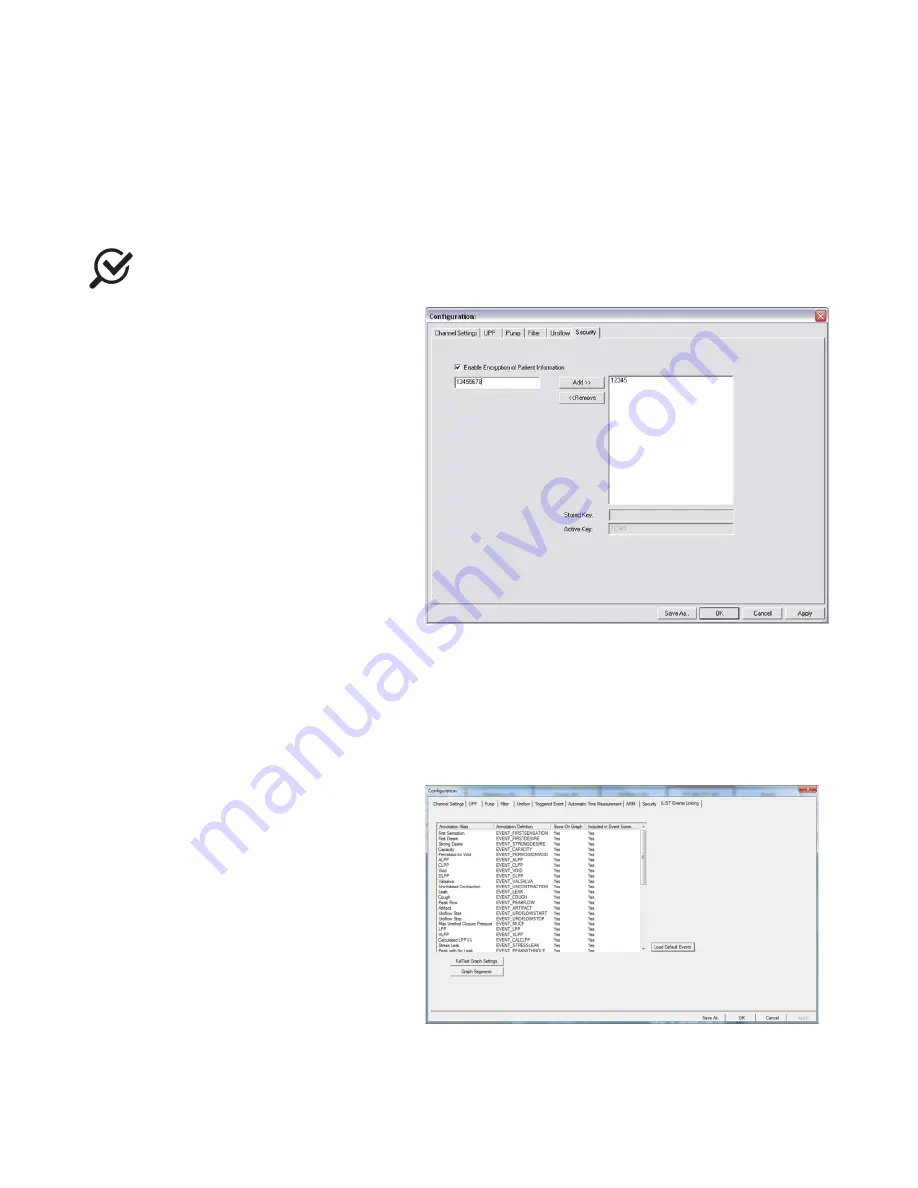
Figure 8 – Configuration Window, Security Tab 

Once a UDS test is performed, remember to select the 

Encrypt Patient Information

 box in the 

Save As

 window. 

Once you save the patient information with encryption, if someone uses a virtual key that is not associated with 
the file they will see the word 

ENCRYPTED

 in all the 

Patient Information

 fields. 

ILIST EVENTS LINKING 

Events that are not in the 

ILIST Events Linking

 may not appear in some of the printed reports. 

Try the following to check if an event is available 
in the Event Summary: 


1.


In the software click Config > Set 

up/Modify. 

2.


Click the 

ILIST Events Linking

 tab. 

3.


(optional) Click the Load Default Events 
button to add the standard iLIST events to 

the listing. 


iLIST Office Reporter will display only the events that appear in the list under this tab. Also, the 

Annotation Alias


needs to exactly match what you mark on the UDS test in order to appear in the 

Event Summary

Summary of Contents for UROCAP IV

Page 1: ...LABORIE Urocap IV Owner s Manual UC4 UM01 V13 00 UROCAP IV Owner s Manual Standalone Model...

Page 2: ...gistered trademark of the Wi Fi Alliance MOTOROLA and product images are trademarks or registered trademarks of Motorola Trademark Holdings LLC ASUS and product images are trademarks or registered tra...

Page 3: ...Consideration of Waste Disposal 14 4 Device Setup 14 4 1 Perform an Equipment Check 14 4 2 Set Up Equipment 16 4 3 Install Software 16 4 4 Connect Urocap IV to Software 16 4 5 Wireless Printer Setup 1...

Page 4: ...4 5 Uroflow Options 34 6 5 Options Menu 35 6 5 1 Test Restart 35 6 5 2 Test Playback 35 6 5 3 Uroflow Auto Start 36 6 5 4 Cursor Value Indicator 36 6 5 5 Digital Value Indicator 36 6 5 6 Control Panel...

Page 5: ...ed in Urodynamic Testing 64 Common Acronyms 65 LIST OF FIGURES Figure 1 Do not immerse the Urocap IV 12 Figure 2 Cleaning the Urocap IV 12 Figure 3 Urocap IV charging port location 13 Figure 4 Urocap...

Page 6: ...Uroflow Study using Automatic Flow Detection 45 Table 16 Performing the Uroflow Study Utilizing Manual Start 46 Table 17 Troubleshooting Urocap IV Usage 50 Table 18 Troubleshooting Bluetooth Connecti...

Page 7: ...Throughout the manual you will also find specially marked sections that emphasize important reminders and information to help you understand the features of the system as marked here CAUTION Provides...

Page 8: ...you with the installation use and operation of the Urocap IV Uroflowmeter For further information or technical service please contact your local LABORIE sales representative or contact LABORIE For wa...

Page 9: ...ransport storage or handling that could in any way hamper its use DO NOT STAND anywhere on the system or its devices The devices are not designed to support the weight of a person DO NOT immerse the U...

Page 10: ...and other conductive parts including those connected to protective earth to prevent damage or injury Do not plug or unplug devices or pair or unpair Bluetooth devices while the Urocap IV system is in...

Page 11: ...ving on to more advanced Urodynamic studies such as Pressure or Micturition The Urocap IV is intended for use in Uroflowmetry studies that measure both flow rate and voided volume and is intended for...

Page 12: ...le Attention must be paid to prevent damage The Urocap IV should be cleaned using a damp cloth with alcohol soap or disinfectant detergent Figure 1 Do not immerse the Urocap IV Figure 2 Cleaning the U...

Page 13: ...f misuse abuse or damage is suspected or any form of mechanical damage to the casing is visible discontinue use and contact LABORIE service If there is a sudden change to the battery s ability to hold...

Page 14: ...ny visible signs of damage or mishandling Notify the carrier immediately if damage has been found Carrying cases and cartons should be saved to provide a convenient and safe way to return the equipmen...

Page 15: ...Table 1 Standard Equipment EQUIPMENT DESCRIPTION Wireless Printer The wireless printer connects to mobile devicess via WIFI and provides a printout of test results Please speak with a Laborie represen...

Page 16: ...Urocap IV the beaker the commode chair and funnel can be set up in one room while the laptop and printer can be in another room collecting and printing data 4 3 INSTALL SOFTWARE If not already install...

Page 17: ...r the system 6 Click Cancel in the Bluetooth Device Server window 7 Click Device Search again 8 Wait for the Urocap to be located When the Urocap is located in the Bluetooth Device Server window highl...

Page 18: ...or the connection to establish and finalize Table 3 Connecting Urocap IV to the Software When the Urocap IV is connected and functioning the Urocap IV Device Manager window will look similar to this 4...

Page 19: ...from the Home screen touch Wireless 2 Touch Settings 3 Touch Wireless Setup Wizard or Wi Fi Protected Setup 4 Follow the display instructions to complete the setup If you are already using the printer...

Page 20: ...Direct password on the printer control panel display from the Home screen touch Wi Fi Direct 4 Proceed to step 5 if the printer has been installed and connected to the computer over a wireless network...

Page 21: ...s Connect the printer and the computer with a USB cable This USB port is at the rear of the printer Note A USB connection between the computer and printer can only be used if these two devices are iso...

Page 22: ...ing Green Battery good c Orange Charger plugged in and battery charging d Blinking Orange Low battery time to charge e Light OFF Battery empty 5 2 CONNECTION STATUS Icon indicators in the Urocap IV De...

Page 23: ...battery is being charged Before complete drainage of the battery power the device s LED lights will flash the battery power status as outlined on page 22 When the battery reaches total power drainage...

Page 24: ...resolve connection issues Calibration button press to apply settings during the calibration process This behaves in the same way as the Apply button in the software Figure 4 Urocap IV Main Controls 6...

Page 25: ...o view all tests associated with that particular patient To view a test click on the test name in the lower half of the window and then click Open Selected Test 6 2 2 OPEN FROM DATA FILE Select this t...

Page 26: ...ins the patient s name comments file date and the procedure date for quick look up The Index file can be re generated by re indexing 6 2 7 ABOUT UDS CLIENT The About UDS Client dialog box displays the...

Page 27: ...he Channel Title box and type a new channel title name To change the Maximum and Minimum scale click the Scale Min or Scale Max box of a channel and type the desired value for the Min and the Max valu...

Page 28: ...nformation 4 Click the Add button to add the serial number to the secure list 5 Click Apply to save selections Figure 8 Configuration Window Security Tab Once a UDS test is performed remember to selec...

Page 29: ...the Event Annotation box 6 3 3 UNLOCK CFG To prevent the accidental overwriting of test configuration files this option will let you lock unlock configuration files All configuration files provided i...

Page 30: ...ll open click Cancel to continue with the test If a previous patient s information is still visible in this form click New Patient and then enter the necessary information Click OK when complete 6 4 2...

Page 31: ...rate with Laborie s software and the built in Liverpool Nomograms To view the Liverpool Nomogram click Info X Y Plot Liverpool Nomogram The Liverpool Nomogram contains the graphical representation of...

Page 32: ...ts by use of the Control Panel event buttons or by right mouse click on the graph window when you want to add the event An event marker will be shown on the Graph window Refer to the following table f...

Page 33: ...the graph move to the point that corresponds to that particular event Figure 15 Using and Adapting Event Markers If you would like to change the appearance of the Event Summary window contents you can...

Page 34: ...the voided volume is less than 55 cc and more than 555 cc Parameters of urinary flow were analyzed from 150 curves from subjects between 20 and 40 years old The minimum normal for a given volume appe...

Page 35: ...tent in definition Normally the default settings for threshold are not changed for performing Uroflowmetry on patients Consult with your LABORIE representative for modifications to default settings TO...

Page 36: ...s and select Cursor Value Indicator or Press the F9 key on the keyboard 6 5 5 DIGITAL VALUE INDICATOR The Digital Value window displays the data of channels with digital attributes While all channels...

Page 37: ...tton in the UDS Client screen Enter the name of the function button using the keyboard Repeat until all the function buttons are labeled appropriately Definition of the name on the function button Cli...

Page 38: ...nnels to zero Patient Info N A Patient Info Opens Patient Info Plot Pre set with the selections made when button is configured Plot Click the plot button to open the Nomograms that are applicable to t...

Page 39: ...trol Panel Settings 2 Click the drop down button of the Control Panel Set Name box and select the appropriate name 3 Click OK To add a new Control Panel set by duplicating the settings of an existing...

Page 40: ...ed In our example we will add an image to the Uroflow button 3 In the Properties window click the Browse button in the Image section to locate the image Our picture in this example will be a picture o...

Page 41: ...Control Panel buttons with the same color and font In the All Buttons section at the bottom of the window select the button property to change and then click the rectangle next to the property to sele...

Page 42: ...scale value Type the new channel scale value and press Enter on the keyboard Table 11 Modifying Graph Appearance To change the order of the channels 1 Right click directly on the channel area and sele...

Page 43: ...e double arrow pointer to another position on the graph 4 Left click and then click the Yes button to move the event Table 13 Adjusting Event Marker Location To change one or more fonts for displaying...

Page 44: ...commode chair and funnel over the Urocap IV and beaker Make sure the beaker and the funnel are aligned but not touching 7 Turn on the computer and then turn on the printer 8 Invite the patient to get...

Page 45: ...e floor or on an approved Uroflow transducer stand 5 Gently place a graduated beaker on top of the Urocap IV 6 Place the commode chair and funnel over the Urocap IV and beaker Make sure the beaker and...

Page 46: ...and complete click the Print button on the control panel if auto start Reporter is not active to open and print reports generated with the test data Select the items to include in the printout and cli...

Page 47: ...listing of the types of reports you can select to view for the particular test file You can also select the report based on the type of test performed The Toolbar contains quick access buttons for fu...

Page 48: ...ation 7 Click Close when calibration complete Figure 21 Calibrating the Urocap IV with UDS120 10 QUICK REFERENCE AND FAQ How do I check that the Urocap IV is connected You can check equipment connecti...

Page 49: ...owmeter No power on electrical outlet Plug into a known working outlet Damaged power cord Unplug and contact LABORIE for replacement cord Power cord not connected properly Ensure power cord is secure...

Page 50: ...ssage on screen reads Calibration Failure Flow out of range Water was poured into beaker too quickly Pour water slowly and at a steady rate More than 500 ml poured into beaker 500 ml must be poured in...

Page 51: ...too soon after computer was turned on Close the Device Manager software Wait several minutes and re open the software to reconnect Table 19 Understanding Error Messages 11 4 PRINTER SYMPTOM S POSSIBLE...

Page 52: ...on condensing Pressure 700 hPa to 1060 hPa up to 2000m Table 21 Equipment Specifications CLASSIFICATIONS Table 22 Classification IEC 60601 1 Class I Equipment Type BF Applied Parts Mode of Operation C...

Page 53: ...rrent Direct Current Table D 1 1 2 Indicates use of Direct Current Non ionizing electromagnetic Radiation 5140 4 Radio Frequency RF Transmitting Device Indicates presence of RF transmitters Humidity L...

Page 54: ...cs Limits and methods of measurement IEC 61000 3 2 2009 Limits for harmonic current emissions equipment input current 16 A per phase IEC 61000 3 3 2013 Limits Limitation of voltage changes voltage flu...

Page 55: ...CC Rules Operation is subject to the following two conditions 1 this device may not cause harmful interference and 2 this device must accept any interference received including interference that may c...

Page 56: ...Electromagnetic environment guidance RF Emissions CISPR 11 Group 1 The Urocap IV uses RF energy only for its internal function Therefore its RF emissions are very low and are not likely to cause any i...

Page 57: ...upply or a battery Power Frequency Magnetic Field 50 60 Hz IEC 61000 4 8 30 A m 30 A m Power frequency magnetic fields should be at levels characteristic of a typical location in a typical commercial...

Page 58: ...e frequency range 150 kHz to 80 MHz field strengths should be less than 3 V m Table 28 Electromagnetic Environment Immunity Requirements Compliance and Guidance for RF Transmitting Devices IEC 60601 1...

Page 59: ...facturer NOTE 1 At 80 MHz and 800 MHz the separation distance for the higher frequency range applies NOTE 2 These guidelines may not apply in all situations Electromagnetic propagation is affected by...

Page 60: ...T Preferences Uroflow Report 1 page voiding study report Preferences UDS Report Full UDS Report Preferences Graph Pages Report Pages Graph pages of UDS report with Report pages Standard Report Prints...

Page 61: ...id squares Print Range Default Prints test from beginning to end Apply Click this button to set up a default configuration when printing each test Graph Scaling 1 Page Graph Graph page is condensed in...

Page 62: ...16 4 22 0 16 7 11 4 11 1 7 8 4 6 24 1 17 7 11 4 290 32 9 24 8 16 7 22 3 17 0 11 7 11 2 7 9 4 6 24 4 18 1 18 4 300 33 2 25 1 16 9 22 6 17 3 12 0 11 3 8 0 4 7 24 8 18 4 12 0 310 33 4 25 3 17 2 22 9 17...

Page 63: ...5 20 4 26 2 20 3 14 4 9 1 6 6 4 1 19 3 14 7 10 0 290 38 8 29 8 20 7 26 5 20 6 14 7 9 2 6 7 4 2 19 7 15 0 10 3 300 39 1 30 0 21 0 26 8 20 8 14 9 9 3 6 8 4 3 20 0 15 3 10 6 310 39 3 30 3 21 2 27 0 21 1...

Page 64: ...and treatment This group sets standards for Urodynamic testing that all LABORIE training follows lower urinary tract symptoms LUTS these may include frequency urgency incontinence nocturia recurrent u...

Page 65: ...oftware LPP Leak point pressure LUTS Lower urinary tract symptoms MCC Maximum cystometric capacity MUCP Maximum urethral closure pressure MUP Maximum urethral pressure NGB Neurogenic bladder Pabd Abdo...

Reviews: