background image

TRANSMISSION

RTV1140CPX, WSM

2-S46

Tooth Contact between 6T Spiral Bevel Pinion Shaft and 37T
Spiral Bevel Gear

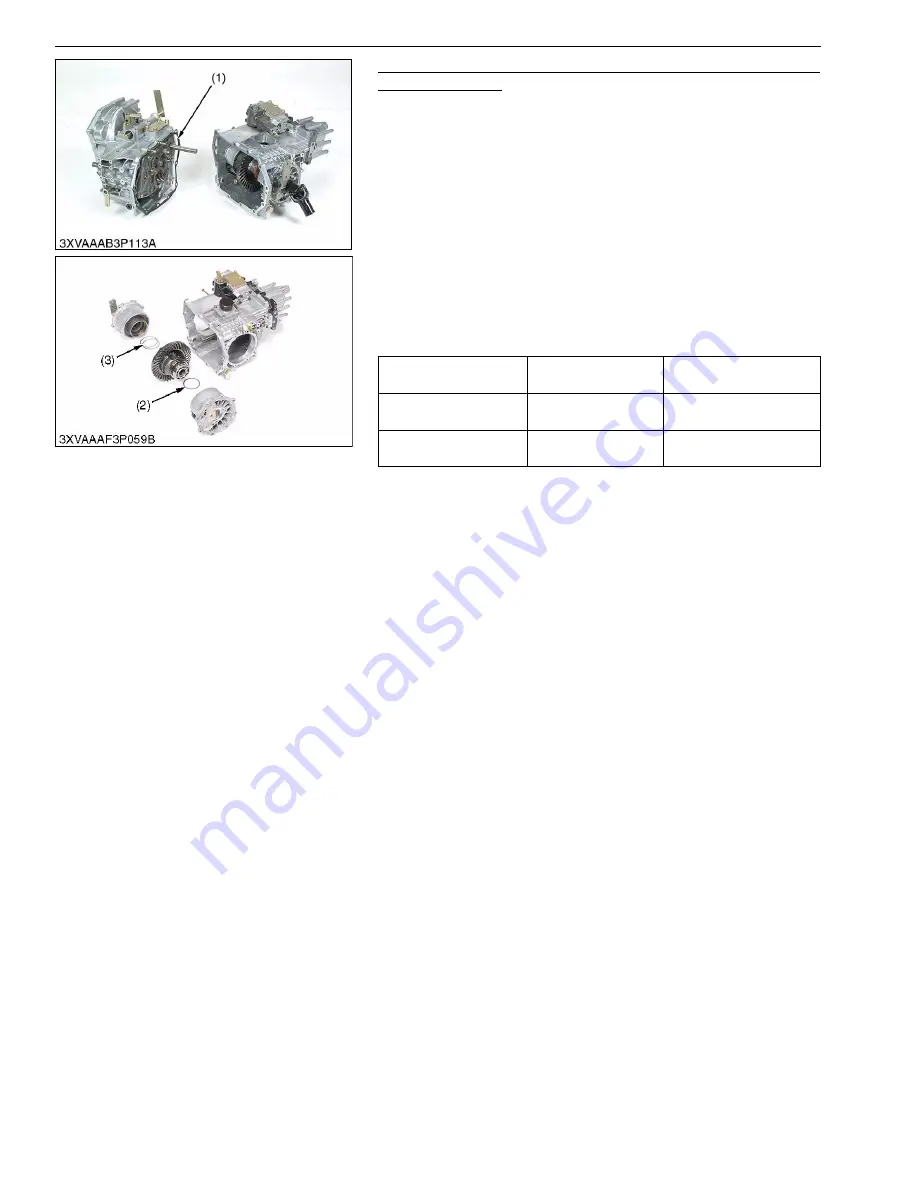
• Use the transmission gasket (1) of the same thickness as the

origin first.

• Use same number of shims as before disassembling.

1. Apply red lead (or prussian blue) lightly on the teeth of spiral

bevel pinion shaft.

2. Reassemble the front case and transmission case.

In this time, set the differential lock shiftier to lock position

3. Tighten the transmission case mounting screw and nut to

specified torque.

4. Temporarily install the propeller shaft assembly and make the

propeller shaft back and forth by 2 to 3 rotations.

5. Check the tooth contact, if not proper, adjust according to the

instructions below.

(Reference)

• Thickness of gasket

0.30 mm (0.012 in.)
0.50 mm (0.020 in.)
0.80 mm (0.031 in.)
1.0 mm (0.039 in.)

• Thickness of shims (2) (LH)

0.10 mm (0.0039 in.)
0.20 mm (0.0079 in.)
0.30 mm (0.012 in.)
0.50 mm (0.020 in.)

• Thickness of shims (3) (RH)

0.10 mm (0.0039 in.)
0.20 mm (0.0079 in.)
0.30 mm (0.012 in.)
0.40 mm (0.016 in.)
0.50 mm (0.020 in.)
0.60 mm (0.024 in.)
0.70 mm (0.028 in.)

(To be continued)

Thickness of gasket (1)

Factory specification

0.50 mm
0.020 in.

Thickness of shim (LH)

Factory specification

0.70 or 0.80 mm 
0.028 or 0.031 in.

Thickness of shim (RH)

Factory specification

0.70 or 0.80 mm 
0.028 or 0.031 in.

(1) Gasket
(2) Shim (LH)

(3) Shim (RH)

KiSC issued 05, 2014 A

Summary of Contents for RTV1140CPX

Page 1: ...RTV1140CPX WORKSHOP MANUAL UTILITY VEHICLE KiSC issued 05 2014 A...

Page 2: ...tinue with the subsequent sections make sure that you read this section Refer to the latest version of Workshop Manual Code No 9Y021 01870 9Y021 18200 for the diesel engine tractor mechanism that this...

Page 3: ...ion Search word to find all the revised locations Last digit of the Code No Issue month Main Revised Point and Corrective Measures Search word Reference Page 2 2014 05 The topic of steering cylinder i...

Page 4: ...I INFORMATION KiSC issued 05 2014 A...

Page 5: ...CONTENTS 1 SAFETY FIRST I 1 2 SAFETY DECALS I 4 3 SPECIFICATIONS I 12 4 TRAVELING SPEEDS I 13 5 DIMENSIONS I 14 INFORMATION KiSC issued 05 2014 A...

Page 6: ...n disengaged positions Do not start the engine when you stay on the ground Start the engine only from operator s seat 9Y1210301INI0004US0 SAFETY FIRST This symbol the industry s Safety Alert Symbol is...

Page 7: ...ou disconnect hydraulic or fuel lines Tighten all connections before you apply the pressure Do not open a fuel system under high pressure The fluid under high pressure that stays in fuel lines can cau...

Page 8: ...ions when you discard oil fuel coolant electrolyte and other dangerous waste 9Y1210301INI0008US0 PREVENT ACID BURNS Keep electrolyte away from your eyes hands and clothing Sulfuric acid in battery ele...

Page 9: ...LS The following safety decals are installed on the machine If a decal becomes damaged illegible or is not on the machine replace it The decal part number is listed in the parts list WSM000001INI0013U...

Page 10: ...INFORMATION RTV1140CPX WSM I 5 9Y1210293INI0002US0 KiSC issued 05 2014 A...

Page 11: ...INFORMATION RTV1140CPX WSM I 6 9Y1210293INI0003US0 KiSC issued 05 2014 A...

Page 12: ...INFORMATION RTV1140CPX WSM I 7 9Y1210293INI0004US0 KiSC issued 05 2014 A...

Page 13: ...INFORMATION RTV1140CPX WSM I 8 9Y1210293INI0005US0 KiSC issued 05 2014 A...

Page 14: ...INFORMATION RTV1140CPX WSM I 9 9Y1210293INI0006US0 KiSC issued 05 2014 A...

Page 15: ...INFORMATION RTV1140CPX WSM I 10 9Y1210293INI0007US0 KiSC issued 05 2014 A...

Page 16: ...y with a soft cloth 3 Replace damaged or missing danger warning and caution labels with new labels 4 If a component with danger warning and caution label s affixed is replace with new part make sure n...

Page 17: ...DeDion axle with leaf springs and shock absorber Dimensions Length 3480 mm 137 0 in Width 1550 mm 61 0 in Height overall 2000 mm 78 7 in Front tread centers 1150 mm 45 3 in HDWS ATV 1180 mm 46 5 in T...

Page 18: ...INFORMATION RTV1140CPX WSM I 13 4 TRAVELING SPEEDS At rated engine rpm 9Y1210293INI0011US0 Rear gear shift lever km h mph Low 13 8 Medium 25 16 High 40 25 Reverse 16 10 KiSC issued 05 2014 A...

Page 19: ...INFORMATION RTV1140CPX WSM I 14 5 DIMENSIONS 9Y1210293INI0012US0 KiSC issued 05 2014 A...

Page 20: ...G GENERAL KiSC issued 05 2014 A...

Page 21: ...4 1 DAILY CHECK G 14 2 CHECK POINTS OF INITIAL 50 HOURS G 20 3 CHECK POINTS OF EVERY 50 HOURS G 24 4 CHECK POINTS OF EVERY 100 HOURS G 27 5 CHECK POINTS OF EVERY 200 HOURS G 32 6 CHECK POINT OF EVERY...

Page 22: ...hour meter reading 9Y1210293GEG0003US0 1 CYLINDER NUMBER The cylinder numbers of KUBOTA diesel engine are designated as shown in the figure The sequence of cylinder numbers is given as No 1 No 2 and...

Page 23: ...BOTA genuine parts for parts replacement to maintain machine performance and to assure safety Gaskets and O rings must be replaced during reassembly Apply grease to new O rings or oil seals before ass...

Page 24: ...or a fee Do not attempt to modify or remodel any electrical parts and wiring When removing the battery cables disconnect the negative cable first When installing the battery cables connect the positiv...

Page 25: ...uired 9Y1210301GEG0024US0 In installing a part take care not to get wiring caught by it 9Y1210301GEG0025US0 After installing wiring check protection of terminals and clamped condition of wiring only c...

Page 26: ...ng the battery remove it from the machine Before recharging remove cell caps Do recharging in a well ventilated place where there is no open flame nearby as hydrogen gas and oxygen are formed 9Y121030...

Page 27: ...male connector being too open WSM000001GEG0076US0 Make sure that plastic cover is large enough to cover whole connector WSM000001GEG0077US0 5 HANDLING OF CIRCUIT TESTER Use tester correctly following...

Page 28: ...symbol of shows color with stripe s An example Red stripe on white color W R WSM000001GEG0079US0 Color of wiring Color code Black B Brown Br Green G Gray Gy or Gr Blue L Light Green Lg Orange Or Pink...

Page 29: ...0 4 Transmission case 11 L 2 9 U S gals 2 4 Imp gals KUBOTA UDT or SUPER UDT fluid 5 Front axle case 0 6 L 0 6 U S qts 0 5 Imp qts KUBOTA UDT or SUPER UDT fluid 6 Knuckle case Ref 0 15 L Ref 0 16 U S...

Page 30: ...North America Therefore please use No 2 D S500 or S15 diesel fuel as an alternative to No 2 D or use No 1 D S500 or S15 diesel fuel as an alternative to No 1 D if outside air temperature is below 10...

Page 31: ...29 to 33 32 to 34 3 2 to 3 5 24 to 25 48 to 55 4 9 to 5 7 36 to 41 40 to 44 4 0 to 4 5 29 to 32 61 to 70 6 2 to 7 2 45 to 52 M12 63 to 72 6 4 to 7 4 47 to 53 78 to 90 7 9 to 9 2 58 to 66 63 to 72 6 4...

Page 32: ...61 to 11 6 16 3 to 19 7 1 66 to 2 01 12 0 to 14 6 5 16 23 1 to 27 7 2 35 to 2 83 17 0 to 20 5 33 to 39 3 4 to 4 0 24 to 29 3 8 48 to 56 4 9 to 5 8 35 0 to 42 0 61 to 73 6 3 to 7 4 45 to 54 1 2 110 to...

Page 33: ...see Warranty Statement in detail No Item Indication of Hour Meter After 700 hrs Refer ence page Impor tant 50 100 150 200 250 300 350 400 450 500 550 600 650 700 1 Engine oil Change every 200 hrs G 2...

Page 34: ...Check every 300 hrs G 35 30 Front axle case oil Change every 400 hrs G 35 31 Knuckle case oil Change every 400 hrs G 36 32 Engine valve clearance Adjust every 800 hrs G 36 33 Fuel injection nozzle in...

Page 35: ...ting CAUTION Be sure to check and service the vehicle on a level surface with the engine shut off and the parking brake ON and implement lowered to the ground if equipped 9Y1210293GEG0005US0 Walk Arou...

Page 36: ...fueling If should spill wipe it off at once or it may cause a fire To prevent water condensation from accumulating in the fuel tank fill the tank before parking overnight NOTE No 2 D is a distillate f...

Page 37: ...screw it into filling hole and remove dipstick again If the level is too low add new oil to the prescribed level at the filling plug with dipstick 1 See page G 8 IMPORTANT If oil level is low do not...

Page 38: ...freeze and water in the specified mixing ratio up to the full level See Flush Cooling System and Changing Coolant in this section IMPORTANT If the radiator cap has to be removed follow the caution ab...

Page 39: ...rk 9Y1210293GEG0013US0 Checking Parking Brake 1 Pull the parking brake lever to apply the brakes With the key switch at ON position the parking brake indicator on the instrument panel lights up To rel...

Page 40: ...eplace the new one See page 5 S22 9Y1210293GEG0019US0 Checking Tire Inflation Pressure Though the tire pressure is factory set to the prescribed level it naturally drops slowly in the course of time T...

Page 41: ...notch on the dipstick See page G 8 9Y1210293GEG0021US0 Replacing Engine Oil Filter CAUTION Be sure to stop the engine before changing the oil filter cartridge Allow engine to cool down sufficiently oi...

Page 42: ...e engine for a few minutes stop the engine and check the oil level again add oil to the prescribed level 8 Make sure that the transmission fluid does not leak past the seal on the filters 9 Install th...

Page 43: ...g Brake Lever 1 Release the parking brake 2 Loosen the lock nut and adjust the cable wire length 3 Tighten the lock nut 2 and check the free play 4 If free play is outside of specifications adjust the...

Page 44: ...the brake seals See page 4 S11 9Y1210293GEG0028US0 Checking Brake Hose and Pipe 1 Check to see that brake hose and pipe are not swollen hardened or cracked 2 Check the brake hose 1 and pipe joints fo...

Page 45: ...do not operate the vehicle Preparation before testing 1 Place all control levers in the NEUTRAL position 2 Set the parking brake and stop the engine Test Range gear shift lever safety switch 1 Sit on...

Page 46: ...tremely wet and muddy conditions lubricate grease fittings more often To be continued 1 Parking Brake Pivot Spray Type Grease 2 Battery Terminal 3 Cargo Lift Cylinder Pivot Spray Type Grease 4 Cargo B...

Page 47: ...cone Grease 1 Apply a small amount of silicone grease to the accelerator wire 1 every 50 hours 9Y1210293GEG0033US0 8 4WD Lever Pivot Spray Type Grease 9 Rear Drive Shaft Grease Fitting 10 VHT Pressure...

Page 48: ...spark arrester 3 is located inside of the exhaust pipe and is fastened with two screws 2 2 Unfasten the bolt and remove the spark arrester 3 3 Shake loosened particles out of the screen assembly and...

Page 49: ...ive Keep open sparks and flames away from the battery at all times especially when charging the battery When charging the battery ensure the vent caps are securely in place if equipped When disconnect...

Page 50: ...until the deflection of the belt falls within acceptable limits 5 Replace alternator belt if it is damaged 9Y1210293GEG0038US0 Adjusting VHT Neutral Spring 1 Park the vehicle on a flat place 2 Set th...

Page 51: ...brake and stop the engine 4 Measure distance between tire beads at front of tire at hub height 5 Measure distance between tire beads at fear of tire at hub height 6 Front distance should be shorter th...

Page 52: ...ss of service period 3 If the fuel line and clamps are found to be damaged or deteriorated replace them 4 Remove the under guard 5 Check fuel filter if it is clogged by debris or contaminated with wat...

Page 53: ...moved Be sure to refit the cover with the arrow on the rear of cover upright If the cover is improperly fitted evacuator valve will not function and dust will adhere to the element Do not touch the se...

Page 54: ...filling plug clean with a rag and screw it into filling hole Remove filling plug again to see if the oil level is between the upper and lower notch 8 After filling reinstall the filling plug 9Y1210293...

Page 55: ...Precaution at Overheating Take the following actions in the event the coolant temperature be nearly or more than the boiling points what is called Overheating 1 Stop the machine operation in a safe pl...

Page 56: ...e for a few minutes stop the engine and check the oil level again add oil to prescribed level IMPORTANT Do not operate the vehicle immediately after changing the transmission fluid Run the engine at m...

Page 57: ...n KUBOTA SUPER UDT OIL on the rubber seal of the new filter 5 Quickly tighten the filter until it contacts the mounting surface then with a filter wrench tighten it an additional 1 turn only 6 After r...

Page 58: ...cing Fuel Hose See page G 31 9Y1210293GEG0067US0 Replacing Radiator Hose Water Pipes See page G 34 9Y1210293GEG0068US0 Replacing Intake Air Line See page G 34 9Y1210293GEG0069US0 Replacing Inner Parts...

Page 59: ...clean water and anti freeze until the coolant level is just below the radiator cap Install the radiator cap securely 7 Fill with fresh water up to the FULL mark on the recovery tank 8 Start and operat...

Page 60: ...out coolant completely or mix fresh water with long life coolant and fill the radiator and recovery tank with the mixture 1 Long life coolant hereafter LLC comes in several types Use ethylene glycol...

Page 61: ...to change the coolant every 2 years NOTE The above data represent industry standard that necessitate a minimum glycol content in the concentrated antifreeze When the coolant level drops due to evapora...

Page 62: ...low blow fuses are intended to protect the electrical cabling If any of them have blown out be sure to pinpoint the causes Never use any substitute use only a KUBOTA genuine part Replacement procedure...

Page 63: ...lb 9Y1210293GEG0082US0 Light Capacity Head lights 37 5 W Tail light 5 W Brake light 21 W Easy Checker 3 8 W 14 V 0 27 A Turn signal light front 20 W if equipped Turn signal light rear 21 W if equipped...

Page 64: ...th piston rings into the cylinder WSM000001GEG0012US0 Piston Ring Tool Code No 07909 32121 Application Use exclusively to remove or install the piston ring with ease WSM000001GEG0013US0 Diesel Engine...

Page 65: ...utter Code No 07909 33102 Application Use to reseat valves Angle 0 79 rad 45 0 26 rad 15 Diameter 28 6 mm 1 13 in 31 6 mm 1 24 in 35 0 mm 1 38 in 38 0 mm 1 50 in 41 3 mm 1 63 in 50 8 mm 2 00 in WSM000...

Page 66: ...eck the fuel injection pressure and spray pattern of nozzle Measuring range 0 to 50 MPa 0 to 500 kgf cm2 0 to 7200 psi WSM000001GEG0021US0 Plastigauge Code No 07909 30241 Application Use to check the...

Page 67: ...296 to 0 299 in dia G 25 mm dia 0 98 in dia H 7 70 to 8 00 mm dia 0 304 to 0 314 in dia I 5 mm 0 2 in J 20 mm dia 0 79 in dia K 13 5 to 13 8 mm dia 0 532 to 0 543 in dia L 8 90 to 9 10 mm 0 351 to 0 3...

Page 68: ...9 in dia G 47 90 to 47 95 mm dia 1 8858 to 1 8878 in dia H 43 90 to 43 95 mm dia 1 7283 to 1 7303 in dia C1 Chamfer 1 0 mm 0 039 in C2 Chamfer 2 0 mm 0 079 in C0 3 Chamfer 0 3 mm 0 012 in A 130 mm 5 1...

Page 69: ...916 50401 4 Threaded Joint 07916 50341 5 Adaptor B M18 P1 5 07916 50361 6 Adaptor C PS3 8 07916 50371 7 Adaptor D PT1 8 07916 50381 8 Adaptor E PS3 8 07916 50392 9 Adaptor F PF1 2 07916 62601 10 Adapt...

Page 70: ...50 in B 12 7 mm 0 50 in J 3 3 mm dia 0 13 in dia R 25 4 mm 1 0 in C 38 1 mm 1 50 in K 50 8 mm 2 0 in S 0 52 rad 30 D 12 7 mm 0 50 in L 127 0 mm 5 0 in T R6 4 R0 25 E 63 5 mm 2 50 in M 381 0 mm 15 0 in...

Page 71: ...O 3 3 mm 0 13 in B 69 9 mm 2 75 in I 203 2 mm 8 0 in P 28 7 mm dia 1 13 in dia C 25 4 mm dia 1 00 in dia J 317 5 mm 12 5 in Q 280 2 mm 11 03 in D 1 4 in thick rubber strip K 190 5 mm 7 5 in R 50 8 mm...

Page 72: ...ia 0 551 in dia P 38 mm dia 1 496 in dia b 40 mm 1 575 in E 22 mm dia 0 866 in dia Q 50 mm 1 969 in c 30 mm 1 181 in F 28 mm dia 1 102 in dia R 5 mm 0 197 in d 24 mm 0 945 in G 32 mm dia 1 260 in dia...

Page 73: ...E 50 mm dia 1 969 in dia R 19 mm 0 748 in e 1 mm 0 039 in F 10 mm dia 0 394 in dia S 17 mm 0 669 in f 6 5 mm 0 256 in G 9 1 to 9 3 mm dia 0 359 to 0 366 in T 10 mm 0 393 in g Chamfer 0 5 mm 0 020 in H...

Page 74: ...ipment Always maintain the correct tire pressure Do not inflate tires above the recommended pressure as shown next page IMPORTANT Do not use tires other than those approved by KUBOTA 9Y1210293GEG0089U...

Page 75: ...ng from use with improper implements are not covered by the warranty Rolling weight Trailer weight Cargo load Above mentioned specifications are based on level ground condition 9Y1210293GEG0091US0 Tir...

Page 76: ...sible Cargo Load IMPORTANT Cargo Bed Capacity CBC is 500 kg 1100 lbs for 1 row seating mode and 300 kg 661 lbs for 2 row seating mode Never carry loads exceeding the Permissible Cargo Load PCL NOTE Ma...

Page 77: ...1 ENGINE KiSC issued 05 2014 A...

Page 78: ...CONTENTS 1 ENGINE BODY 1 M1 2 LUBRICANTING SYSTEM 1 M2 3 COOLING SYSTEM 1 M3 4 FUEL SYSTEM 1 M4 MECHANISM KiSC issued 05 2014 A...

Page 79: ...e of blow by gas into the atmosphere After its oil content is filtered by oil shield 4 the blow by gas is fed back to the intake manifold through breather valve 3 to be used for re combustion 9Y121029...

Page 80: ...5 idle gear 6 governor shaft 5 camshaft 13 and rocker arm shaft 3 to lubricate each part Some part of oil splashed by the crankshaft or leaking and dropping from gaps of each part lubricates these par...

Page 81: ...er block 7 And the coolant flows to the transmission oil cooler through cylinder block 7 Also the coolant flows to the air conditioner unit from the water pump 4 when the water valve in the air condit...

Page 82: ...40 to 150 kgf cm2 1990 to 2133 psi of the injection nozzle 1 is injected into the combustion chamber Part of the fuel fed to the injection nozzle 1 lubricates the moving parts of the needle valve insi...

Page 83: ...PARATION 1 S19 1 Removing Outer Components 1 S19 2 Separating Rear Axle 1 S24 3 Separating Transmission Assembly 1 S25 4 Separating Engine 1 S27 3 DISASSEMBLING AND ASSEMBLING 1 S27 1 External Compone...

Page 84: ...crew glow plug and nozzle holder 1 S28 1 S30 Improper valve timing Correct or replace timing gear 1 S34 Piston ring and cylinder worn Repair or replace 1 S36 Excessive valve clearance Adjust 1 S11 Sta...

Page 85: ...orn Replace piston 1 S49 Valve stem and valve guide worn Replace 1 S41 Oil leaking due to defective seals or packing Replace Fuel Mixed into Lubricant Oil Injection pump s plunger worn Replace 1 S33 D...

Page 86: ...8 Radiator net and radiator fin clogged with dust Clean Inside of radiator corroded Clean or replace G 17 Coolant flow route corroded Clean or replace G 17 Radiator cap defective Replace Overload run...

Page 87: ...Clearance O D I D 0 035 to 0 065 mm 0 0014 to 0 0025 in 6 960 to 6 975 mm 0 2741 to 0 2746 in 7 010 to 7 025 mm 0 2760 to 0 2765 in 0 10 mm 0 0039 in Valve Face Angle Intake Angle Exhaust 1 0 rad 60...

Page 88: ...e Gear 1 Side Clearance 0 20 to 0 51 mm 0 0079 to 0 020 in 0 80 mm 0 031 in Camshaft Side Clearance Alignment 0 070 to 0 22 mm 0 0028 to 0 0086 in 0 30 mm 0 012 in 0 01 mm 0 0004 in Cam Height Intake...

Page 89: ...15 mm 0 0059 in Crankshaft Side Clearance Alignment 0 15 to 0 31 mm 0 0059 to 0 012 in 0 50 mm 0 020 in 0 02 mm 0 0008 in Crankpin to Crankpin Bearing Crankpin Crankpin Bearing Oil Clearance O D I D...

Page 90: ...Idle Speed At Rated Speed More than 49 kPa 0 5 kgf cm2 7 psi 197 to 441 kPa 2 00 to 4 50 kgf cm2 28 5 to 64 0 psi 147 kPa 1 50 kgf cm2 21 3 psi Inner Rotor to Outer Rotor Clearance 0 060 to 0 18 mm 0...

Page 91: ...0 0 kgf cm2 1991 psi Delivery Valve Fuel Tightness 10 seconds 13 73 12 75 MPa 140 0 130 0 kgf cm2 1991 1849 psi 5 seconds 13 73 12 75 MPa 140 0 130 0 kgf cm2 1991 1849 psi Injection Nozzle Injection P...

Page 92: ...ion case bottom set screw 39 2 to 44 1 4 00 to 4 49 29 0 to 32 5 Transmission case side set screw 62 7 to 72 5 6 40 to 7 39 46 3 to 53 4 Engine set screw 48 0 to 55 9 4 90 to 5 70 35 4 to 41 2 Engine...

Page 93: ...nder 7 If the measurement is below the allowable limit apply a small amount of oil to the cylinder wall through the glow plug hole or nozzle hole and measure the compression pressure again 8 If the co...

Page 94: ...he rear end plate so that the No 1 piston comes to the overlap position 6 Check the following valve clearance marked with using a feeler gauge 7 If the clearance is not with in the factory specificati...

Page 95: ...clogged Oil gallery clogged Excessive oil clearance Foreign matter in the relief valve When reassembling After checking the engine oil pressure tighten the engine oil pressure switch to the specified...

Page 96: ...tions loosen the alternator mounting screws and relocate the alternator to adjust 9Y1210293ENS0011US0 Alternator Belt Damage and Wear 1 Check the belt for damage 2 If the belt is damaged replace it 3...

Page 97: ...air with the radiator cement When water leak is excessive replace the radiator 9Y1210293ENS0015US0 Thermostat Valve Opening Temperature 1 Suspend the thermostat in the water by a string with its end i...

Page 98: ...d 1TC 10 and 20 for the crank angle before the top dead center of No 1 cylinder 8 If injection timing is out of adjustment readjust the timing with shims NOTE The liquid gasket is not required for ass...

Page 99: ...ure to the injection pump pressure tester 2 Refer to the figure 5 Set the speed control lever to the maximum speed position 6 Run the starter to increase the pressure 7 If the pressure can not reach t...

Page 100: ...is less than allowable limit replace the pump with new one or repair with a Kubota authorized pump service shop NOTE Never try to disassemble the injection pump assembly For repairs you must contact...

Page 101: ...ut 7 with a vise 2 Remove the nozzle holder 1 and take out parts inside When reassembling Assemble the nozzle in clean fuel Install the push rod 4 noting its direction After assembling the nozzle be s...

Page 102: ...cable 3 from the battery 4 9Y1210293ENS0025US0 Cargo Bed 1 Lift up the cargo bed 1 by hand and support it with the safety support so that the hydraulic cylinder should not drop 2 Remove the cotter pin...

Page 103: ...ter and anti freeze until the coolant level is just below the radiator cap Install the radiator cap securely Fill with fresh water up to the FULL mark on the recovery tank Start and operate the engine...

Page 104: ...tely into the oil pan 5 After draining reinstall the drain plug 6 Install the under guard When refilling Fill with new KUBOTA SUPER UDT fluid up to the upper notch on the dipstick See page G 8 How to...

Page 105: ...ling 9Y1210293ENS0029US0 Wiring Harness 1 Disconnect the wiring harness from engine glow plug 1 coolant temperature switch 2 engine stop solenoid 3 and oil pressure switch 4 2 Disconnect the wiring ha...

Page 106: ...able 4 Adjust the length of differential lock cable 7 Adjust the length of parking brake cables 5 9 Adjust the length of 4WD shift cable 11 NOTE See 1 CHECKING AND ADJUSTING on page 2 S6 9Y1210293ENS0...

Page 107: ...ounting bolt 3 and flange nut and remove the rear axle bracket assembly 5 by use the axle support 6 When reassembling Align the master spline of propeller shaft and rear axle shaft Replace the boot ba...

Page 108: ...a manner as to insert two bolts in the from and then two bolts in the rear instead of inserting the four bolts at a time When reassembling the transmission and engine one piece assembly mission frame...

Page 109: ...93ENS0038US0 Tightening torque Transmission case bottom set screw 39 2 to 44 1 N m 4 00 to 4 49 kgf m 29 0 to 32 5 lbf ft Transmission case side set screw 62 7 to 72 5 N m 6 40 to 7 39 kgf m 46 3 to 5...

Page 110: ...nsmission case Apply anti fretting grease NISSEKI PYRONOC UNIVERSAL N6C or its equivalents to splines of engine output shaft 9Y1210293ENS0039US0 3 DISASSEMBLING AND ASSEMBLING 1 External Components Ex...

Page 111: ...holder assemblies 4 3 Remove the copper gasket 5 and heat seal 6 4 Remove the lead 2 from the glow plugs 3 5 Remove the glow plugs 3 When reassembling Replace the copper gasket and heat seal with new...

Page 112: ...njection nozzle gasket must be changed when the injection nozzle is removed for cleaning or for service 9Y1210293ENS0044US0 Rocker Arm and Push Rod 1 Remove the rocker arm bracket nut 2 Detach the roc...

Page 113: ...using a torque wrench correctly tighten the cylinder head screws to correct torque figure The different type of screw 4 is used for the positions j and n in illust 9Y1210293ENS0046US0 Tappets 1 Remov...

Page 114: ...ase and Timing Gears Oil Pan and Oil Strainer 1 Remove the oil pan mounting screws 2 Remove the oil pan 2 3 Remove the oil strainer 1 When reassembling After cleaning the oil strainer check to see tha...

Page 115: ...l Plate 1 Remove the engine stop solenoid 2 Remove the speed control plate 1 3 Remove the governor spring 2 Be careful not to drop spring into crankcase When reassembling Apply a liquid gasket Three B...

Page 116: ...reassembling When installing the injection pump insert the control rack pin 2 firmly into the groove 6 of the thrust lever of fork lever NOTE Addition or reduction of shim 0 05 mm 0 002 in delays or...

Page 117: ...y to the fuel camshaft 7 before installation Make sure to assemble the external snap ring 8 of the governor shaft 9 Check the governor shaft 9 for smooth rotation IMPORTANT When replacing the ball bea...

Page 118: ...thod as above When reassembling Before inserting the piston into the cylinder apply enough engine oil to the piston When inserting the piston into the cylinder face the mark on the connecting rod to t...

Page 119: ...ing gap 11 Apply engine oil to the piston pin When installing the connecting rod to the piston immerse the piston in 80 C 176 F oil for 10 to 15 minutes and insert the piston pin to the piston When in...

Page 120: ...take a mistake using inside screws and outside screws When reassembling Fit the bearing case gasket 3 and the bearing case cover gasket 4 in the correct location Install the bearing case cover 6 to p...

Page 121: ...il passage in the main bearing cases Apply clean engine oil on the bearings Install the main bearing case assemblies in the original positions Since diameters of main bearing cases vary install them i...

Page 122: ...clearance between the crankpin and crankpin bearing and between the piston pin and small end bushing NOTE After checking the top clearance be sure to assemble the cylinder head with a new cylinder hea...

Page 123: ...r head 9Y1210293ENS0066US0 Clearance between Valve Stem and Valve Guide 1 Remove carbon from the valve stem 2 Measure the valve stem O D with an outside micrometer 3 Measure the valve guide I D with a...

Page 124: ...acement 9Y1210293ENS0068US0 Valve Seat 1 Coat the valve face lightly with prussian blue and put the valve on its seat to check the contact 2 If the valve does not seat all the way around the valve sea...

Page 125: ...them with valve lapping tool 4 Check the valve seat with prussian blue The valve seating surface should show good contact all the way around 9Y1210293ENS0070US0 Valve Lapping 1 Apply compound evenly...

Page 126: ...en Rocker Arm and Rocker Arm Shaft 1 Measure the rocker arm shaft O D with an outside micrometer 2 Measure the rocker arm I D with an inside micrometer and then calculate the oil clearance 3 If the oi...

Page 127: ...If the oil clearance is not correct replace the gear 9Y1210293ENS0077US0 Push rod alignment Allowable limit 0 25 mm 0 0098 in Oil Clearance between tappet and tappet guide bore Factory specification 0...

Page 128: ...tip on the intermediate journal 3 Measure the camshaft alignment 4 If the measurement exceeds the allowable limit replace the camshaft 9Y1210293ENS0080US0 Cam Lobe Height 1 Measure the height of the...

Page 129: ...ar bushing replacing tool Refer to 8 SPECIAL TOOLS in G GENERAL section When installing 1 Clean a new idle gear bushing and idle gear bore and apply engine oil to them 2 Press in a new bushing using a...

Page 130: ...1 Clean a new small end bushing and bore and apply engine oil to them 2 Using a small end bushing replacing tool press in a new bushing service parts taking care to see that the connecting rod oil ho...

Page 131: ...allowable limit replace the connecting rod 9Y1210293ENS0088US0 Piston Ring Gap 1 Insert the piston ring into the lower part of the cylinder the least worn out part with a piston 2 Measure the ring gap...

Page 132: ...one referring to the table and figure Reference Oversize dimensions of crankshaft journal 9Y1210293ENS0091US0 Clearance between piston ring and piston ring groove Second ring Factory specifica tion 0...

Page 133: ...re NOTE Never insert the plastigage into the crankpin oil hole Be sure not to move the crankshaft while the connecting rod screws are tightened Reference Undersize dimensions of crankpin 9Y1210293ENS0...

Page 134: ...n a new bearing 1 2 so that its seam 1 is toward the exhaust manifold side See figure 9Y1210293ENS0095US0 Oil clearance between crankshaft journal and crankshaft bearing 1 Factory specification 0 0340...

Page 135: ...al O D Intermediate Factory specification 47 934 to 47 950 mm 1 8872 to 1 8877 in Crankshaft bearing 2 I D Factory specification 47 984 to 48 029 mm 1 8892 to 1 8909 in Oil clearance between crankshaf...

Page 136: ...cylinder at the six positions see figure with a cylinder gauge to find the maximum and minimum I D s 2 Get the difference Maximum wear between the maximum and the minimum I D s 3 If the wear exceeds t...

Page 137: ...specifications replace the oil pump rotor assembly 9Y1210293ENS0101US0 Clearance between Rotor and Cover 1 Put a strip of plastigage onto the rotor face with grease 2 Install the cover and tighten th...

Page 138: ...2 TRANSMISSION KiSC issued 05 2014 A...

Page 139: ...E 2 M1 2 POWER TRAIN 2 M2 1 HYDROSTATIC TRANSMISSION HST 2 M3 1 Structure 2 M3 2 Oil Flow 2 M5 3 Function of Components 2 M6 2 RANGE GEAR SHIFT SECTION AND FRONT WHEEL DRIVE SECTION 2 M23 MECHANISM Ki...

Page 140: ...TRANSMISSION RTV1140CPX WSM 2 M1 1 STRUCTURE 9Y1210293TRM0001US0 1 Input Shaft Section 2 Hydrostatic Transmission Section 3 Range Shift Gear Section 4 Front Wheel Drive Section KiSC issued 05 2014 A...

Page 141: ...sion of this model consists of a series of gears and shafts as shown in previous page The traveling system is chiefly composed of hydrostatic transmission section range gear shift section and front wh...

Page 142: ...piston motor charge pump servo regulator unload valve and various valves Refer to the next page for detailed parts in the HST 9Y1210293TRM0003US0 1 Input Shaft Pump Shaft 2 Charge Pump 3 Output Shaft...

Page 143: ...lock Pump 10 Port Block Cover 11 Suction Oil Filter Cartridge 12 Charge Relief Valve 13 Control Piston 14 Assist Motor Cover 15 Variable Swashplate Assist Motor 16 Piston 17 Cylinder Block Assist Moto...

Page 144: ...the main circuit also drops and the assist motor 10 returns to its neutral position and just the stationary motor 11 maintains torque to the output shaft 9 Now a closed circuit is formed by the pump 1...

Page 145: ...swashplate 9 Therefore a tilt angle of swashplate is varied by servo piston movement The regulator and the servo piston are connected with feedback lever 5 and the movement of the piston is restricte...

Page 146: ...nses the servo piston position When the spool is at the neutral position the piston adjusting screw 9 serves to position the servo piston so that the pump s variable swashplate gets neutral 9Y1210293T...

Page 147: ...feedback lever As a result the hydraulic circuit is formed as shown here The servo piston is affected by the charge pressure and starts moving in the direction of arrow 9Y1210293TRM0008US0 1 Servo Ad...

Page 148: ...speed up until it gets well balanced with the feedback lever A smaller load on the other hand moves the servo piston toward the speed up side The feedback lever now works on the regulator spool to sw...

Page 149: ...ws back to the HST housing With such circuit formed the servo spring 11 pushes the servo piston back to the neutral position 9Y1210293TRM0010US0 1 Servo Adjusting Screw 2 Regulator Valve Assembly 3 Re...

Page 150: ...is stationary as no oil is being fed from the HST pump 19 Until oil is fed back from the HST pump 19 the cylinder assembly of the stationary motor 13 and assist motor 9 are halted which keeps the outp...

Page 151: ...cylinder block 5 the output shaft 16 starts turning The output shaft rotation is determined by the delivery rate of the HST pump 19 varying the rotation Then the motor oil drops to a low pressure and...

Page 152: ...tarted In this way the output shaft 16 achieves the maximum rpm with the assist motor 8 off as shown in the figure above Then the motor oil drops to a low pressure and returns through the motor port C...

Page 153: ...ort G too As a result the output shaft 16 is driven by the stationary motor 13 and assist motor 8 The output shaft 16 rpm drops in proportion to the tilt of the assist motor variable swashplate 8 wher...

Page 154: ...hplate pump 19 moves toward to the neutral position under the reaction of HST pump 8 itself With the variable swashplate tilted back to neutral side the engine load becomes lighter and the engine rpm...

Page 155: ...force that is exerted to push open the backward travel high pressure relief valve 12 When the dynamic brake is applied the pressure at port D drops below the charge pressure level If the oil from por...

Page 156: ...d the residual pressure in the circuit is relieved through the orifice 23 This operation releases the torque remaining in the transmission As a result smooth shifting of gears is made possible 9Y12102...

Page 157: ...g depending on the pressure oil temperature and other factors With this in mind oil must be constantly Charge relief valve will open when oil pressure exceeds valve operating pressure 9Y1210293TRM0018...

Page 158: ...pressure line serves as a high pressure relief valve If the pressure exceeds a high pressure limit level the spring 3 force and opens the valve seat that is located between the check valve seat 1 and...

Page 159: ...dual pressure in the HST circuit shifting to the neutral position cannot always be fully achieved This time to eliminate this problem an unload valve is employed in the traveling circuit When the brak...

Page 160: ...and forward travelling speed increases Then the swashplate is returned to neutral with the neutral holder arm 4 when the pedal is released The ball bearing 5 on the neutral holder 8 pulled with the ne...

Page 161: ...ing to the neutral position cannot always be fully achieved This time to eliminate this problem an unload valve is employed in the travel circuit When the brake pedal 1 is depressed the unload valve o...

Page 162: ...h the cable linkage of the shift lever at the operator s seat The speed change system is of constant mesh type Front Wheel Drive Section This section is located near the range gear shift section The f...

Page 163: ...ION 2 S17 1 Removing Outer Components 2 S17 2 Separating Rear Axle 2 S23 3 Separating Transmission Assembly 2 S24 4 Separating Engine and Transmission 2 S26 5 Separating Front Case and Transmission Ca...

Page 164: ...oper level G 8 Control linkage or cable defective Repair linkage 2 S22 Charge pressure is too low Solution order 1 Replace oil filter cartridge G 21 2 Check charge pressure 2 S9 3 Inspect or flush cha...

Page 165: ...Position Control linkage is out of adjustment or sticking Repair or replace linkage 2 S22 Adjust neutral position 2 S10 System Operates in One Direction Only Control linkage defective Repair or replac...

Page 166: ...sion fluid used Replenish or change 2 S18 Noise while Turning Differential pinions or differential side gears worn or damaged Replace 2 S32 Differential lock binding does not disengage Replace 2 S31 B...

Page 167: ...1 rpm L Position 106 to 119 min 1 rpm VHT Pressure Release Cable Length L1 Length L2 Clearance L3 14 mm 0 55 in 50 mm 2 0 in 10 5 to 11 0 mm 0 414 to 0 433 in 6T Spiral Bevel Pinion Shaft Turning Tor...

Page 168: ...5 29 to 32 Back idle gear shaft nut 93 2 to 102 9 50 to 10 5 68 8 to 75 9 Bearing holder mounting screw 32 to 34 3 2 to 3 5 24 to 25 Bearing cover mounting screw 18 to 20 1 8 to 2 1 13 to 15 Differen...

Page 169: ...n improper sized allen wrench is used to loose the plug the hex socket section will be damaged and you won t be able to loose the plug 2 Install the HST adaptor and high pressure gauge to P1 port 2 3...

Page 170: ...e plug the hex socket section will be damaged and you won t be able to loose the plug 2 Install the HST adaptor and high pressure gauge to P2 port 2 3 Check to see that parking brake is applied 4 Rais...

Page 171: ...OTE High pressure gauge is 29 4 MPa 300 kgf cm2 4267 psi full scale When reassembling Take care not to damage O ring on plug Condition Engine speed 3000 min 1 rpm Oil temperature 45 to 55 C 113 to 131...

Page 172: ...r weight on the plug slowly paying attention not to damage its hex socket section If the allen wrench is fitted on the plug at a slant or an improper sized allen wrench is used to loose the plug the h...

Page 173: ...adjusting Work by two people when you checking and adjusting neutral NOTE The hex socket plug is securely tightened Therefore it is very important to use a proper sized allen wrench and fit it securel...

Page 174: ...th hex socket head screw 5 Adjusting procedure Adjust to loosen the lock nut 6 on a right side of servo piston and for the adjustment hex socket head screw 5 to make both P1 port 3 and P2 port 4 press...

Page 175: ...epress the speed control pedal 2 and measure the rotations of rear wheel Engine speed is set with tachometer 4 If the measurement is not within the factory specification loosen the lock nut and adjust...

Page 176: ...outer section so that the speed control pedal 7 is positioned in the upper limit where the pedal comes into contact with the stopper Then tighten the lock nut 3 firmly 5 Adjust the height of the speed...

Page 177: ...fitting nuts 9 lever side and link side are tightened 4 Move the main shift arm 5 to right and left to confirm that it is in the neutral position Due to a force of the spring in the main shift arm 5 t...

Page 178: ...s condition put the cable through the cable stay and adjust the length of the cable outer section while taking care not to move the 4WD lever 5 Then tighten the lock nuts 2 firmly Also check that the...

Page 179: ...8 not to loosen NOTE Do not depress the brake pedal while measuring the clearance 7 Adjust for the clearance between the unload linkage 5 and the plug 9 to become L3 of length with the unload cable 8...

Page 180: ...ve cable 3 from the battery 4 9Y1210293ENS0025US0 Cargo Bed 1 Lift up the cargo bed 1 by hand and support it with the safety support so that the hydraulic cylinder should not drop 2 Remove the cotter...

Page 181: ...l with the new KUBOTA SUPER UDT fluid up to the upper notch on the dipstick 2 Refer to LUBRICANTS FUEL AND COOLANT in MAINTENANCE See page G 8 After running the engine for a few minutes stop the engin...

Page 182: ...pletely into the oil pan 5 After draining reinstall the drain plug 6 Install the under guard When refilling Fill with new KUBOTA SUPER UDT fluid up to the upper notch on the dipstick See page G 8 How...

Page 183: ...rate the engine for few minutes Stop the engine and let cool Check coolant level of recovery tank and add coolant if necessary IMPORTANT Do not start engine without coolant Use clean fresh water and a...

Page 184: ...w plug 1 coolant temperature switch 2 engine stop solenoid 3 and oil pressure switch 4 2 Disconnect the wiring harness from transmission safety switch 5 and rotation sensor 6 9Y1210293ENS0030US0 1 Int...

Page 185: ...l cable 4 Adjust the length of differential lock cable 7 Adjust the length of parking brake cables 5 9 Adjust the length of 4WD shift cable 11 NOTE See 1 CHECKING AND ADJUSTING on page 2 S6 9Y1210293E...

Page 186: ...g mounting bolt 3 and flange nut and remove the rear axle bracket assembly 5 by use the axle support 6 When reassembling Align the master spline of propeller shaft and rear axle shaft Replace the boot...

Page 187: ...ch a manner as to insert two bolts in the from and then two bolts in the rear instead of inserting the four bolts at a time When reassembling the transmission and engine one piece assembly mission fra...

Page 188: ...10293ENS0038US0 Tightening torque Transmission case bottom set screw 39 2 to 44 1 N m 4 00 to 4 49 kgf m 29 0 to 32 5 lbf ft Transmission case side set screw 62 7 to 72 5 N m 6 40 to 7 39 kgf m 46 3 t...

Page 189: ...and the transmission case Apply anti fretting grease NISSEKI PYRONOC UNIVERSAL N6C or its equivalents to splines of engine output shaft 9Y1210293ENS0039US0 5 Separating Front Case and Transmission Ca...

Page 190: ...case gasket with new one Replace the shift cover gasket with new one 9Y1210293TRS0016US0 3 DISASSEMBLING AND ASSEMBLING 1 Front Case Disassembling Front Case Assembly 1 Remove the O ring 1 from input...

Page 191: ...with a magnet 3 Tap out the roll pins 2 and remove the springs 8 and detent balls 7 4 Loosen the nut 4 and tap out the back idle shaft 5 to the case side 5 Remove the bearing holder mounting screws an...

Page 192: ...older into the front case by tapping the 11T 12T gear shaft bearing NOTE After inserting the detent ball mount the spring Push the spring inward using a screwdriver or the like and press in the roll p...

Page 193: ...lock bolt for 4WD shift arm 4 4 Draw out the 4WD shaft 5 and input shaft 6 When reassembling Use same number of shim 7 as before disassembling Reference 9Y1210293TRS0019US0 Thickness of shim Factory s...

Page 194: ...fferential lock shaft 3 Remove the differential support cover mounting screws and remove the differential support cover 5 When reassembling Apply liquid gasket Three Bond 1215E Locktite 5699 or equiva...

Page 195: ...ial side gears 10 and differential side gear washers 9 When reassembling Install the differential pinion and differential side gear aligning the parting marks Lock the differential pinion shaft 5 by s...

Page 196: ...n piston 2 springs 4 and stopper rod 3 When reassembling Take care not to damage O ring on the piston case 9Y1210293TRS0024US0 Tightening torque Piston case 69 to 78 N m 7 0 to 8 0 kgf m 51 to 57 lbf...

Page 197: ...t the charge relief valve and spring 11 Be sure set the valve plate 13 to port block cover 10 Thrust ball bearing sequence thin race inside variable swash plate 7 ball bearing open side down thick rac...

Page 198: ...T Valve plate 3 4 may stick to the port block cover but they are not fixed Take care not to drop them And these valve plate are not interchangeable 9Y1210293TRS0026US0 Cylinder Block Pump Assembly 1 R...

Page 199: ...Pump 1 Remove the charge pump mounting screws and remove the charge pump cover 3 2 Remove the rotors 1 2 When reassembling NOTE Align the each alignment mark of rotors Alignment mark should be front...

Page 200: ...the shims 4 spring 3 and poppet 2 3 Remove the valve case 5 When reassembling Take care not to damage the O rings on the valve cover and valve case 9Y1210293TRS0032US0 Tightening torque Hex head socke...

Page 201: ...ove the servo piston assembly mounting hex head screw 2 Pull out the servo piston assembly 2 slightly by the hand When reassembling Replace the gasket with new one NOTE Take care not to do damage the...

Page 202: ...2 2 Disconnect the quick couplers 1 3 Remove the filter bracket 3 with oil filter cartridge and suction hoses When reassembling 9Y1210293TRS0036US0 Tightening torque Oil filter bracket mounting screw...

Page 203: ...motor case 4 and variable swashplate 5 with thrust ball bearing to port block cover 9 Be careful not to loose the spring 6 for charge relief valve Thrust ball bearing sequence thin race inside variab...

Page 204: ...ver but they are not fixed Take care not to drop them And these valve plate are not interchangeable 9Y1210293TRS0038US0 4 SERVICING Cable 1 Check that the cable move smoothly within the cable outer 2...

Page 205: ...d hardened or been otherwise damaged replace the rubber bush 9Y1210293TRS0041US0 Checking Bearing 1 Hold the inner race and push and pull the outer race in all directions to check for wear and roughne...

Page 206: ...ft and gear 9Y1210293TRS0044US0 Taper Roller Bearing 1 Check the bearing for abrasion color change or other damage 2 If there is any doubt as to the condition of a taper roller bearing replace it 9Y12...

Page 207: ...ss of shims 0 10 mm 0 0039 in 0 15 mm 0 0059 in 0 20 mm 0 0079 in 0 30 mm 0 012 in 0 50 mm 0 020 in 9Y1210293TRS0048US0 Backlash between Differential Pinion and Differential Side Gear 1 Secure the dif...

Page 208: ...clearance exceeds the allowable limit replace faulty parts 9Y1210293TRS0051US0 Clearance between differential case and differential side gear Factory specification 0 0500 to 0 151 mm 0 00197 to 0 005...

Page 209: ...make the propeller shaft back and forth by 2 to 3 rotations 5 Check the tooth contact if not proper adjust according to the instructions below Reference Thickness of gasket 0 30 mm 0 012 in 0 50 mm 0...

Page 210: ...side shim 2 and add shim 3 of the same thickness as the right side to left side Replace the transmission gasket 1 with a thicker one to move the spiral bevel pinion shaft forward For move the spiral b...

Page 211: ...h Adjust the backlash properly by repeating the above procedure 9Y1210293TRS0053US0 Return Piston Springs and Stopper Rod 1 Check the springs 3 for breakage and wear 2 Check the return piston 1 for fr...

Page 212: ...mage 4 If anything unusual replace it 9Y1210293TRS0059US0 Charge Relief Valve and Check and High Charge Pressure Relief Valve 1 Check the spring 2 and charge relief valve poppet for scratches breakage...

Page 213: ...7 in per one turn of the poppet 4 4 Repeat the same operation a few times to find the distance A as it is difficult to acquire at the first time 5 After finding the distance A hold the setscrew 6 to a...

Page 214: ...across the valve plate surface If worn it will be defective 6 If worn or scored replace it NOTE After checking coat them with transmission oil Valve plates are not interchangeable 9Y1210293TRS0062US0...

Page 215: ...3 REAR AXLE KiSC issued 05 2014 A...

Page 216: ...CONTENTS 1 STRUCTURE 3 M1 MECHANISM KiSC issued 05 2014 A...

Page 217: ...design to consider riding comfort etc by using the type which uses the gas together with oil After the final reduction power is transmitted to a rear axle 5 through the propeller shaft 6 9Y1210293RAM...

Page 218: ...S2 3 CHECKING DISASSEMBLING AND SERVICING 3 S3 1 CHECKING 3 S3 2 PREPARATION 3 S3 1 Rear Axle Bracket Assembly 3 S3 2 Leaf Spring 3 S5 3 DISASSEMBLING AND ASSEMBLING 3 S7 1 Rear Axle Bracket Assembly...

Page 219: ...m Probable Cause Solution Reference Page Noise when Start Universal joint bearing worn propeller shaft Replace 3 S8 Noise while Forward and Reverse Universal joint bearing worn propeller shaft Replace...

Page 220: ...to 66 4 Slotted nut 190 19 4 140 Leaf spring mounting rod and flange nut 48 0 to 55 9 4 90 to 5 70 35 4 to 41 2 Lock nut 24 0 to 28 0 2 45 to 2 85 17 7 to 20 6 Spring reamer bolt and nut 29 4 to 49 0...

Page 221: ...ually check the rubber bush in the upper and lower mountings of the rear shock absorber 8 If they are worn cracked hardened or otherwise damaged replace them with new one 9Y1210293RAS0003US0 2 PREPARA...

Page 222: ...nut and remove the rear axle bracket assembly 5 by use the axle support 6 When reassembling Align the master spline of propeller shaft and rear axle shaft Replace the boot band 4 with new one Apply a...

Page 223: ...en installing the bush in the mounts of the leaf spring lubricate them with a soapy water CAUTION Do not use engine oil or petroleum distillates to lubricate the bushes because they will deteriorate t...

Page 224: ...pecified torque after setting up the wheel and unloading the machine on ground 9Y1210293RAS0007US0 Tightening torque Shock absorber mounting bolt and nut upper 77 4 to 90 2 N m 7 90 to 9 19 kgf m 57 1...

Page 225: ...as bearing inner and tap it while keeping the bearing when you tap the propeller shaft Moreover there is no problem if the bearing is inserted in the position in which a rear axle can be tightened Aft...

Page 226: ...replace it 9Y1210293RAS0010US0 Checking Propeller Shaft and Rear Axle 1 Visually check the splines of the propeller shaft and rear axle 2 If they are twisted badly worn or chipped replace the propelle...

Page 227: ...4 BRAKES KiSC issued 05 2014 A...

Page 228: ...CONTENTS 1 GENERAL OUTLINE 4 M1 2 KNUCKLE FRONT BRAKE 4 M2 3 REAR BRAKE 4 M3 4 MASTER CYLINDER 4 M4 5 BRAKE OIL 4 M5 6 PARKING BRAKE 4 M6 MECHANISM KiSC issued 05 2014 A...

Page 229: ...d with an enclosed wet multi disc type brake The system consists of brake pedal 5 master cylinder 9 brake hose 2 brake pipe 1 brake cylinder 8 brake piston 4 and other parts 9Y1210293BRM0001US0 1 Brak...

Page 230: ...s and the brake piston moves in the direction of arrow and causing the brake discs to press against the knuckle case At this time the brake seals are deformed in the knuckle case 1 and are subjected t...

Page 231: ...brake oil pressure increases and the brake cylinder 8 is shortened the linkage causes the brake cam lever 2 to turn into the direction of arrow shown in the above figure Therefore the cam plate 7 also...

Page 232: ...r negative pressure To get rid of the negative pressure the brake fluid in the reservoir flows through the supply port b supply chamber and piston end small hole c along the back of the primary cup in...

Page 233: ...Brake Fluid Standard used on automotives and motorcycles When keeping in mind that the UDT oil used for Kubota tractors so far cannot be applied as the brake oil If a coated surface gets stained with...

Page 234: ...of the following Brake cam lever parking brake lever 1 mechanical equalizer 3 and right and left cables etc When pulling the parking brake lever and the rear wheel brakes are applied and the rear axl...

Page 235: ...4 S2 3 TIGHTENING TORQUES 4 S3 4 CHECKING DISASSEMBLING AND SERVICING 4 S4 1 CHECKING AND ADJUSTING 4 S4 2 DISASSEMBLING AND ASSEMBLING 4 S8 1 Front Brake 4 S8 2 Rear Brake 4 S13 3 Master Cylinder As...

Page 236: ...der malfunctioning Repair or replace 4 S15 Brake Drags Brake pedal travel too small Adjust 4 S4 Master cylinder return spring weaken or broken Replace 4 S15 Master cylinder malfunctioning Repair or re...

Page 237: ...ification Allowable Limit Brake Pedal Travel 7 to 14 mm 0 28 to 0 55 in Brake Disc Thickness 3 30 to 3 50 mm 0 130 to 0 138 in 3 00 mm 0 118 in Friction Plate Thickness 1 92 to 2 08 mm 0 0756 to 0 081...

Page 238: ...ted nut 150 15 3 111 Rear wheel mounting screw 75 to 90 7 6 to 9 2 55 3 to 66 4 Tie rod end slotted nut 50 5 1 37 Ball joint mounting screw and nut 48 0 to 55 9 4 90 to 5 70 35 4 to 41 2 Knuckle case...

Page 239: ...nstalled in brake system components and may cause brake failure Avoid contamination of the brake fluid Thoroughly clean area around the filler cap before removing Do not open the brake fluid reservoir...

Page 240: ...k up the front side of machine and remove the front wheels 2 Connect a clear plastic hose 4 to the bleeder 3 running the other end of the hose into a container 3 Pump the brake pedal 5 until it become...

Page 241: ...link length using the turnbuckle 1 so that the brake lever 2 has no play then turnbuckle is returned by 1 4 rotation 3 Adjust the other side Reference Turning torque of the rear axle at this time is 9...

Page 242: ...e cable 2 outer section so that the cable does not pull the brake cam lever 4 5 not activate the brake when the parking brake lever 3 is not pulled and pulls the brake lever activates the brake when t...

Page 243: ...ar either side and finish with the front either side 1 Jack up the front side of machine and remove the front wheels 2 Connect a clear plastic hose 4 to the bleeder 3 running the other end of the hose...

Page 244: ...the stand under the frame front 2 Remove the front wheel 3 Remove the joint guard 4 4 Remove the eye joint bolt for brake hose 1 and drain the brake fluid 5 Remove the cotter pin and remove the slotte...

Page 245: ...slotted nut to the specified tightening torque install a cotter pin as shown in the figure NOTE Tighten the lower arm mounting bolt and nut 3 with the specified torque after setting up the wheel and...

Page 246: ...r brake fluid only The brake seal 3 11 4 10 are used for transmission fluid only Degrease both the piston 7 and the knuckle case 4 before installing each brake seal Before inserting the piston 7 apply...

Page 247: ...0CPX WSM 4 S12 Continued When reassembling Refer to the front page 9Y1210293BRS0012US0 4 Knuckle Case 7 Piston 8 Brake Seal 1 9 Brake Seal 2 10 Brake Seal 4 11 Brake Seal 3 12 Alignment Mark KiSC issu...

Page 248: ...bearing holder 1 3 Remove the brake disk and friction plate When reassembling When installing the internal snap ring to differential support cover 2 as shown in the left photo When installing the bea...

Page 249: ...Lever 1 Remove the actuator 1 and balls 2 2 Remove the external snap ring 3 and remove the cam lever 4 When reassembling Take care not to damage the O ring 9Y1210293BRS0015US0 1 Actuator 2 Ball 3 Ext...

Page 250: ...g hoses wash off with water immediately Brake fluid quickly ruins synthetic resin or rubber hoses NOTE Do not transform and do not damage the brake pipe Do not reuse the drained brake fluid Do not mix...

Page 251: ...valve stem moves smoothly Push in the secondary piston match the slot of the piston with the stop pin 10 installation hole and insert the stop pin 10 Apply a thin coat of special grease COSMO RUBBER G...

Page 252: ...stalled 2 If the measurement is less than the allowable limit replace the cam plate and balls 3 Inspect the ball holes of cam plate for uneven wear 4 If the uneven wear is found replace it 9Y1210293BR...

Page 253: ...ston before inserting it Never use mineral oil grease or the like 9Y1210293BRS0023US0 Dust Seal and O ring 1 If oil leaks from dust seal 2 Remove the internal circlip 2 and remove the dust seal 1 and...

Page 254: ...5 FRONT AXLE KiSC issued 05 2014 A...

Page 255: ...CONTENTS 1 STRUCTURE 5 M1 1 FRONT AXLE 5 M1 2 FRONT SUSPENSION 5 M2 MECHANISM KiSC issued 05 2014 A...

Page 256: ...aft 1 The power is further transmitted through the differential bevel gear 2 and differential side gear 3 to the CV joint 8 and finally reaches the front axle 6 in the knuckles The knuckles and the fr...

Page 257: ...erson strut type suspension is a sort of independent suspension Impacts from the ground are conveyed through the front tires and knuckles 4 and absorbed by the strut 3 The strut does not just serve to...

Page 258: ...MBLING AND SERVICING 5 S4 1 CHECKING AND ADJUSTING 5 S4 2 PREPARATION 5 S5 1 Front Suspension 5 S6 2 Knuckle Case 5 S10 3 Front Differential Case 5 S11 3 DISASSEMBLING AND ASSEMBLING 5 S13 1 Strut 5 S...

Page 259: ...hten 5 S7 Air sucked in power steering circuit Bleed Front Wheels Can Not Be Driven Drive shaft joint broken Replace 5 S10 Front wheel drive gears in transmission broken Replace 2 S30 Front differenti...

Page 260: ...0 00099 to 0 0025 in 32 000 to 32 025 mm 1 2599 to 1 2608 in 32 000 to 32 025 mm 1 2599 to 1 2608 in 31 959 to 31 975 mm 1 2583 to 1 2589 in 0 30 mm 0 012 in Differential Pinion Shaft to Differential...

Page 261: ...ed nut 50 5 1 37 Ball joint mounting and nut 48 0 to 55 9 4 90 to 5 70 35 4 to 41 2 Front axle slotted nut 150 15 3 111 Knuckle case mounting bolt and slotted nut 50 5 1 37 Strut mounting nut 48 0 to...

Page 262: ...ce between tire beads at front of tire at hub height A B 5 Measure distance between tire beads at rear of tire at hub height 9Y1210293FAS0005US0 Toe in Adjusting 1 Loosen the lock nuts 1 2 Turn the ti...

Page 263: ...9Y1210293ENS0025US0 Draining Knuckle Case Oil 1 Park the vehicle on a firm flat and level surface 2 To drain the used oil remove the drain the filling plugs at the LH knuckle case and drain the oil co...

Page 264: ...or KUBOTA SUPER UDT fluid Refer to LUBRICANTS FUEL AND COOLANT See page G 8 9Y1210293FAS0008US0 1 Front Suspension Front Wheel and Front Axle Nut 1 Loosen the front wheel mounting screw 1 When reasse...

Page 265: ...d nut 10 7 Remove the cotter pin and remove the knuckle case mounting bolt and nut 9 8 Separate the strut 1 and knuckle case assembly 4 from lower arm 8 9 Remove the strut mounting nut 12 and then rem...

Page 266: ...the specified torque after setting up the wheel and unloading the machine on ground Tighten the slotted nut to 150 N m 15 3 kgf m 110 lbf ft If the slot and pin hole do not meet tighten the nut until...

Page 267: ...ighten the lower arm mounting bolt and nut 1 with the specified tightening torque after setting up the wheel and unloading the machine on ground 9Y1210293FAS0010US0 Tightening torque Lower arm mountin...

Page 268: ...if the slots in the nut do not align with the cotter pin hole in the tie rod end ball joint and knuckle case mounting bolt tighten the nut clockwise up to next alignment It should be within 30 degree...

Page 269: ...from lower arm 8 and strut 1 10 Remove the drive shaft assembly 11 from front differential case 16 11 Remove the differential side cover 13 12 Disconnect the propeller shaft 14 from pinion shaft 13 R...

Page 270: ...gure Apply anti fretting grease NISSEKI PYRONOC UNIVERSAL N6C or its equivalents to spline of propeller shaft 14 and pinion shaft NOTE Tighten the lower arm mounting bolt and nut 3 with the specified...

Page 271: ...strut mount bracket 1 spring 4 plates spacer spring upper support 2 and stopper 5 When reassembling Set the spring end to the bulge 8 in the lower spring seat the strut damper Set the spring end to th...

Page 272: ...6 When reassembling Be sure insert the external snap ring Replace the oil seal with new one Take care not to damage the O ring Insert the bearing 7 and oil seal 8 first to the knuckle cover and then i...

Page 273: ...1 Remove the right and left bearings 1 from the differential case 9Y1210293FAS0016US0 Bevel Gear 1 Remove the bevel gear UBS screws 1 2 Remove the bevel gear 2 from differential case 3 When reassembli...

Page 274: ...o the taper roller bearings 10 and install them correctly noting their direction Replace the lock nut 2 and oil seal 8 with new ones After tighten the lock nut 2 to the turning torque stake it firmly...

Page 275: ...020US0 Clearance between Differential Case Spiral Bevel Gear and Differential Side Gear 1 Measure the differential side gear boss O D with an outside micrometer 2 Measure the differential case I D and...

Page 276: ...torque of bevel pinion shaft 3 If the turning torque is not within the factory specifications adjust with the lock nut NOTE After turning force adjustment be sure to stake the lock nut 9Y1210293FAS002...

Page 277: ...tooth contact at 1 3 of the entire width from the small end 9Y1210293FAS0025US0 Change the adjusting collar to smaller size and change the adjusting collar to larger size For move the spiral bevel ge...

Page 278: ...8 in 0 3 mm 0 012 in 0 5 mm 0 020 in Thickness of shims 2 RH 0 1 mm 0 004 in 0 2 mm 0 008 in 0 3 mm 0 012 in 0 5 mm 0 020 in Thickness of adjusting collars 3 4 3 4 mm 0 134 in 3 6 mm 0 142 in 3 8 mm 0...

Page 279: ...aks or distortion 4 If the lower arm is damaged is any way replace it When reassembling Install the lower arm rubber bush with press machine and lower arm bush tool 1 1 2 2 4 4 NOTE Use soapy water wh...

Page 280: ...e 4 Separate the joint outer and drive shaft assembly 5 Remove the external snap ring 8 and then remove the steel ball 9 steel ball retainer 11 and steel ball base 10 6 Remove the boot DOJ 4 of front...

Page 281: ...1 Unlock the both boot bands 2 3 and remove the boot BJ 1 of knuckle case side 2 Wipe the old grease NOTE The knuckle case side wheel side joint can not be disassembled To be continued 1 Boot BJ 2 Bo...

Page 282: ...al grease is the boot kit When install the internal circlip 2 so that the opening 1 is aligned with one of the projections 3 as shown in the figure left Install the steel ball retainer 5 as shown in t...

Page 283: ...6 STEERING KiSC issued 05 2014 A...

Page 284: ...CONTENTS 1 STRUCTURE 6 M1 2 HYDRAULIC CIRCUIT 6 M2 3 STEERING CONTROLLER 6 M3 4 STEERING CYLINDER 6 M5 MECHANISM KiSC issued 05 2014 A...

Page 285: ...sed of steering wheel steering controller steering cylinder and other components shown in the figure 9Y1210293STM0001US0 1 Steering Wheel 2 Steering Controller 3 Power Steering Oil Tank 4 Return Hose...

Page 286: ...er 2 steering cylinder etc An oil tank dedicated for power steering is located below the operator s seat The oil in this tank is fed by the hydraulic pump driven by engine to the steering controller 3...

Page 287: ...ough the metering device 2 Namely when the rotor is driven two chambers suck in oil due to volumetric change in the pup chambers formed between the rotor 11 and the stator 12 while oil is discharged f...

Page 288: ...f valve 1 is located in the steering controller It controls the maximum pressure of the power steering system Its setting pressure is as follows 8 0 to 9 0 MPa 82 to 91 kgf cm2 1200 to 1300 psi 9Y1210...

Page 289: ...g movement to both front wheels The steering cylinder provide force in both directions Depending upon direction the steering wheel is turned pressure oil enters at one end of the cylinder to extend or...

Page 290: ...CING 6 S4 1 CHECKING 6 S4 2 PREPARATION 6 S5 1 Separating Power Steering Controller 6 S5 2 Separating Power Steering Cylinder 6 S7 3 Separating Hydraulic Pump 6 S8 4 Removing Power Steering Hose 6 S10...

Page 291: ...nctioning Replace 6 S5 Front Wheels Wander to Right and Left Steering controller malfunctioning Replace 6 S5 Air sucked in pump due to lack of oil Replenish G 8 Air sucked in pump from suction circuit...

Page 292: ...SM 6 S2 2 SERVICING SPECIFICATIONS POWER STEERING BODY 9Y1210293STS0002US0 Item Factory Specification Allowable Limit Relief Valve Operating Pressure 8 0 to 9 0 MPa 82 to 91 kgf cm2 1200 to 1300 psi K...

Page 293: ...62 16 0 to 18 9 Steering controller mounting screw 23 5 to 27 4 2 40 to 2 79 17 4 to 20 2 Tie rod end slotted nut 50 5 1 37 Steering cylinder bracket mounting screw 103 to 117 10 5 to 12 0 76 0 to 86...

Page 294: ...above mentioned lock position NOTE After set a pressure gauge be sure to bleed air Note that the pressure value changes by the pump action of the power steering controller when the steering operation...

Page 295: ...rom the battery 4 9Y1210293ENS0025US0 Bonnet Upper 1 Remove the snap pin and remove the bonnet upper 3 2 Remove the ROPS pipes 1 3 Lift ROPS boots and remove the three screws on both sides 4 Remove th...

Page 296: ...and four wheel drive lever grip 6 4 Disconnect the connector for main switch horn switch and head light switch 5 Remove the panel mounting screws 5 and the panel support 6 Disconnect the all connector...

Page 297: ...e cotter pin hole in tie rod end tighten the nut clockwise up to next alignment If should be within 30 degree Loosen once and tighten again when the slit goes past the nearest hole After tightening th...

Page 298: ...the oil completely into the oil pan 5 After draining reinstall the drain plug 6 Install the under guard When refilling Fill with new KUBOTA SUPER UDT fluid up to the upper notch on the dipstick See p...

Page 299: ...ry first 1 Set the seat to 1 row 2 Remove the battery cover 1 3 Remove the air cleaner hose 2 4 Disconnect the negative cable 3 from the battery 4 9Y1210293ENS0025US0 Air Cleaner 1 Remove the air clea...

Page 300: ...rom the battery first When connecting connect the positive cable to the battery first 1 Set the seat to 1 row 2 Remove the battery cover 1 3 Remove the air cleaner hose 2 4 Disconnect the negative cab...

Page 301: ...drive lever grip 6 4 Disconnect the connector for main switch horn switch and head light switch 5 Remove the panel mounting screws 5 and the panel support 6 Disconnect the all connectors from panel an...

Page 302: ...7 and center step 8 When reassembling 9Y1210293STS0012US0 Tightening torque Seat belt inside mounting nut 48 0 to 55 9 N m 4 90 to 5 70 kgf m 35 4 to 41 2 lbf ft Seat belt outside mounting nut 13 0 to...

Page 303: ...otch on the dipstick After running the engine for few minutes stop it and check the oil level again if low add oil to prescribed level Use KUBOTA UDT fluid or SUPER UDT fluid Refer to LUBRICANTS FUEL...

Page 304: ...nternal circlip 8 6 Remove the cylinder head 6 from the cylinder tube 2 7 Remove the piston rod 1 When reassembling NOTE Seals must be exchanged after disassembling Apply transmission fluid to the exc...

Page 305: ...ydraulic Pump Oil Seal 1 Remove the internal snap ring 2 and remove the oil seal 1 When reassembling If the oil seal is defective worn or scratched replace it 9Y1210293STS0016US0 1 Oil Seal 2 Internal...

Page 306: ...7 HYDRAULIC SYSTEM KiSC issued 05 2014 A...

Page 307: ...1 2 HYDRAULIC CIRCUIT 7 M2 1 HYDRAULIC CARGO BED LIFT 7 M2 3 HYDRAULIC PUMP 7 M3 4 HYDRAULIC CONTROL VALVE 7 M4 1 RELIEF VALVE 7 M4 2 FLOATING WITH DETENT VALVE 7 M5 5 HYDRAULIC CYLINDER 7 M7 MECHANIS...

Page 308: ...cylinder oil tank and other components as shown in the figure 9Y1210293HYM0001US0 1 Hydraulic Oil Tank 2 Delivery Hose 3 Hydraulic Pump 4 Return Hose 5 Hydraulic Lift Cylinder Lever 6 Oil Filter Cart...

Page 309: ...g functions 1 Oil is supplied by hydraulic pump which is driven by the governor shaft in the engine Therefore hydraulic pump starts running when engine is started 2 The hydraulic pump forces out the o...

Page 310: ...ur gears drive gears 4 7 and driven gears 5 6 Hydraulic pump is driven by the governor shaft in the engine Maximum displacement is as follows 9Y1210293HYM0003US0 Displacement Factory specification Fro...

Page 311: ...r through the clearance between the guide surface and the seat so that the chamber provides a damping effect controlling valve vibration When the pressure in the circuit rises the pressure in the damp...

Page 312: ...irection of the arrow the pressure fed oil in the P port opens the check valve 1 and flows to the implement cylinder via B port Return oil from the implement cylinder flows from the A port to the tran...

Page 313: ...on the spool 2 moves to extreme right the detent ball 3 and detent sleeve 4 holds the spool 1 at the floating position as shown in the figure The pressure fed oil from the hydraulic pump flows to oil...

Page 314: ...er is single double type and it is installed directly between main frame arm cargo bed The main components of the hydraulic cylinder are shown in the figure 9Y1210293HYM0004US0 1 Piston Nut 2 Piston S...

Page 315: ...TING 7 S4 1 Hydraulic Control Valve Pump and Cylinder 7 S4 2 PREPARATION 7 S5 1 Separating Hydraulic Pump 7 S5 2 Separating Hydraulic Cylinder 7 S7 3 Hydraulic Control Valve 7 S8 3 DISASSEMBLING AND A...

Page 316: ...n O ring or cylinder damaged Replace 7 S10 Noise Suction hose loosen or broken Repair or replace 7 S7 Insufficient hydraulic lift oil Refill 7 S5 Relief valve setting pressure too low Adjust or replac...

Page 317: ...rature 45 to 55 C 113 to 131 F Setting Pressure 14 5 to 15 5 MPa 148 to 158 kgf cm2 2110 to 2240 psi Item Factory Specification Allowable Limit Tip of Gear Tooth and Casing Clearance 0 15 mm 0 0059 in...

Page 318: ...e retaining nut 22 to 25 2 3 to 2 5 17 to 18 Hydraulic cylinder tube retaining nut 22 to 25 2 3 to 2 5 17 to 18 Delivery hose retaining nut 35 to 41 3 6 to 4 1 26 to 30 Adaptor for hydraulic cylinder...

Page 319: ...factory specifications adjust with the adjusting shims 4 Condition Engine speed 3000 min 1 rpm Oil temperature 45 to 55 C 113 to 131 F Reference Replace the hydraulic pump if pressure does not rise in...

Page 320: ...g and drain the oil completely into the oil pan 5 After draining reinstall the drain plug 6 Install the under guard When refilling Fill with new KUBOTA SUPER UDT fluid up to the upper notch on the dip...

Page 321: ...attery first 1 Set the seat to 1 row 2 Remove the battery cover 1 3 Remove the air cleaner hose 2 4 Disconnect the negative cable 3 from the battery 4 9Y1210293ENS0025US0 Air Cleaner 1 Remove the air...

Page 322: ...le from the battery first When connecting connect the positive cable to the battery first 1 Set the seat to 1 row 2 Remove the battery cover 1 3 Remove the air cleaner hose 2 4 Disconnect the negative...

Page 323: ...oosen the lock nut 4 and remove the hinge bolt 5 and nut 9Y1210293ENS0001US0 Hydraulic Cylinder 1 Disconnect the hydraulic hoses 2 2 Remove the hydraulic cylinder 1 9Y1210293HYS0004US0 3 Hydraulic Con...

Page 324: ...en reassembling If the oil seal is defective worn or scratched replace it 9Y1210293STS0016US0 Tightening torque Hydraulic cylinder tube retaining nut 22 to 25 N m 2 3 to 2 5 kgf m 17 to 18 lbf ft Deli...

Page 325: ...not to damage the O ring on the cylinder head 9Y1210293HYS0006US0 Cylinder Head Piston and Nut 1 Secure the rod end in a vise 2 Unscrew the nut 4 and remove the piston 3 and cylinder head 2 from the p...

Page 326: ...s of scoring of damage Install the spool and spacer to the valve housing using care not to damage the O ring 9Y1210293HYS0007US0 1 O ring 2 Back Up Ring 3 Collar 4 Spring Holder 5 Spring 6 Spring Hold...

Page 327: ...exceeds the allowable limit replace it 9Y1210293HYS0013US0 Side Plate Thickness 1 Measure the side plate thickness with an outside micrometer 2 If the thickness is less than the allowable limit repla...

Page 328: ...8 ELECTRICAL SYSTEM KiSC issued 05 2014 A...

Page 329: ...NGINE STOP SOLENOID 8 M5 3 CHARGING SYSTEM 8 M6 1 ALTERNATOR 8 M7 2 IC REGULATOR 8 M7 4 LIGHTING SYSTEM 8 M8 5 COOLING SYSTEM 8 M9 1 FAN MOTOR 8 M10 2 COOLANT TEMPERATURE SWITCH 8 M10 6 GAUGES 8 M11 1...

Page 330: ...ELECTRICAL SYSTEM RTV1140CPX WSM 8 M1 1 WIRING DIAGRAM KiSC issued 05 2014 A...

Page 331: ...gine The main switch automatically returns to the ON position the terminal BAT is connected only to the terminal ON thereby causing the starting circuit to be opened stopping the starter motor When th...

Page 332: ...a reduction type The speed of the pinion gear is reduced to approximately one third of motor one 9Y1210293ELM0002US0 1 Armature 2 Yoke 3 Brush Holder 4 End Frame 5 Gear 6 Drive End Frame 7 Pinion 8 R...

Page 333: ...e temperature of the resistor the flowing current is reduces to prevent the heater 4 from being heated The ignition point is in the area of 2 to 3 mm 0 079 to 0 118 in from the tip of the plug in orde...

Page 334: ...the plunger 2 move to left side so that the movement of control rack becomes free when the battery current stops the plunger 2 is returned to the original position by the spring to keep the control ra...

Page 335: ...c power for various electrical devices and also charges the battery while the engine runs This alternator has IC regulator 9Y1210293ELM0006US0 1 Battery 2 Main Switch 3 Slow Blow Fuse 50 A 4 Slow Blow...

Page 336: ...tment is eliminated Since there are no moving parts IC regulators are extremely durable and resistant to vibration The overheat compensation characteristics ensure that the control voltage is reduced...

Page 337: ...s etc 9Y1210293ELM0009US0 1 Battery 2 Main Switch 3 Slow Blow Fuse 60 A 4 Slow Blow Fuse 50 A 5 Fuse 15 A 6 Fuse 15 A 7 Combination Switch 8 Head Light Switch 9 Blinker Switch 10 Horn Switch 11 Flashe...

Page 338: ...consists of coolant temperature switch relay fan motor etc 9Y1210293ELM0010US0 1 Battery 2 Main Switch 3 Slow Blow Fuse 60 A 4 Slow Blow Fuse 50 A 5 Fuse 30 A 6 Fuse 10 A 7 Radiator Fan Relay 8 Coolan...

Page 339: ...SWITCH The coolant temperature switch is installed to the water flange of engine and its tip is in touch with the coolant The fan motor rotates when the coolant temperature goes up more than the speci...

Page 340: ...mperature sensor for the coolant temperature detection 9Y1210293ELM0013US0 1 Battery 2 Main Switch 3 Slow Blow Fuse 60 A 4 Slow Blow Fuse 50 A 5 Fuse 10 A 6 Fuse 5 A 7 Fuse 15 A 8 Fuse 5 A 9 Combinati...

Page 341: ...r head of engine and its tip is in touch with the coolant It contains a thermistor 4 whose electrical resistance decreases as the temperature increases Current varies with changes in the coolant tempe...

Page 342: ...rking Brake Brake Fluid Lamp When apply parking brake or brake fluid low level this lamp illuminates 2 Charge Lamp When the charging system is not functioning properly this lamp illuminates 3 Oil Pres...

Page 343: ...n Switch 8 S9 3 Starter 8 S11 4 Glow Plug 8 S12 5 Safety Switch 8 S13 6 Engine Stop Solenoid 8 S13 7 Alternator 8 S14 8 Lighting System 8 S15 9 Cooling System 8 S18 10 Gauges 8 S21 11 Relays 8 S24 12...

Page 344: ...ative cable disconnected or improperly connected Repair or replace 8 S8 Slow blow fuse blown Replace G 41 Fuse Blown Frequently Short circuited Repair or replace Symptom Probable Cause Solution Refere...

Page 345: ...nected or improperly connected between main switch ACC terminal and engine stop solenoid Repair or replace Engine stop solenoid defective Replace 8 S13 Stop solenoid relay defective Replace 8 S24 Engi...

Page 346: ...G 42 Wiring harness disconnected or improperly connected Repair or Replace Hazard Light Does Not Flicker If Equipped Flasher unit defective Replace Turn Signal Light Does Not Light If Equipped Fuse b...

Page 347: ...Light Fuse blown 5 A Replace G 41 Bulb blown Replace G 42 Parking light switch defective Repair or Replace 8 S17 Wiring harness disconnected between parking light switch and parking light Repair or Re...

Page 348: ...Function Coolant temperature gauge defective Replace 8 S23 Coolant temperature sensor defective Replace 8 S22 Wiring harness disconnected or improperly connected between coolant temperature gauge and...

Page 349: ...erence of O D s Undercut Length 30 0 mm 1 18 in Less than 0 02 mm 0 0008 in 0 50 to 0 80 mm 0 020 to 0 031in 14 0 mm 0 551 in 29 0 mm 1 14 in 0 05 mm 0 002 in 0 20 mm 0 0079 in 9 0 mm 0 35 in Combinat...

Page 350: ...ee page G 10 9Y1210293ELS0003US0 Item N m kgf m lbf ft Starter B terminal nut 5 9 to 11 0 60 to 1 2 4 4 to 8 6 Alternator Pulley nut 58 4 to 78 9 5 95 to 8 05 43 1 to 58 2 ROPS pipe mounting bolt and...

Page 351: ...garded damage to alternator and regulator may result 9Y1210293ELS0004US0 1 Battery Battery Voltage 1 Stop the engine and turn the main switch off 2 Connect the COM lead of the voltmeter to the battery...

Page 352: ...210293ELS0007US0 Connector Voltage 1 Measure the voltage with a voltmeter across the connector B red terminal and chassis 2 If the voltage differs from the battery voltage 11 to 14 V the wiring harnes...

Page 353: ...an ohmmeter across the B terminal and the G terminal and measure the resistance across the B terminal and the ACC terminal 3 If 0 ohm is not indicated these contacts of the main switch are faulty 4 Ma...

Page 354: ...nal post 7 If the motor does not run check the motor 9Y1210293ELS0010US0 Magnet Switch Test Pull in Holding Coils 1 Remove the motor from the starter housing 2 Preparate a 6 V battery for the test 3 C...

Page 355: ...battery voltage the wiring harness or main switch is faulty 9Y1210293ELS0012US0 Glow Plug Continuity 1 Disconnect the lead from the glow plugs 2 Measure the resistance with an ohmmeter between the glo...

Page 356: ...jumper leads from the engine stop solenoid body to the battery negative terminal 6 When switch 6 is turn on the plunger pulls into the solenoid body and then turn off the switch 6 the plunger comes o...

Page 357: ...switch OFF Measure the voltage between the B terminal 1 and the chassis 2 Turn the main switch ON Measure the voltage between the IG terminal 3 and the chassis 9Y1210293ELS0018US0 1 B Terminal 2 Alter...

Page 358: ...Connector Terminal Voltage 1 Disconnect the connector from the combination switch 1 after turning the main switch OFF 2 Turn the main switch ON and measure the voltage with a voltmeter across the con...

Page 359: ...021US0 Engine Oil Pressure Switch Continuity 1 Measure the resistance with an ohmmeter across the switch terminal and the chassis 2 If 0 ohm is not indicated in the normal state the switch is faulty 3...

Page 360: ...ELS0023US0 Parking Brake Switch Continuity 1 Measure the resistance with an ohmmeter across the switch terminal and the chassis 2 If 0 ohm is not indicated in the normal state the switch is faulty 3 I...

Page 361: ...the coolant temperature switch 2 after turning the main switch OFF 2 Turn the main switch ON and connect a jumper lead 5 from the connector terminal 1 3 to the connector terminal 2 4 3 If the fan mot...

Page 362: ...an 83 C 181 F the switch is faulty 3 If 0 ohms is not indicated when the coolant temperature is higher than 87 to 93 C 189 to 199 F the switch is faulty 9Y1210293ELS0026US0 Resistance At coolant tempe...

Page 363: ...t a jumper lead from the terminal 3 to the battery positive terminal post 3 Connect a jumper lead momentarily between the 2 terminal 4 and the battery negative terminal post 4 If the fan motor does no...

Page 364: ...voltage the wiring harness or meter panel is faulty 2 Sensor Continuity 1 Remove the fuel level sensor from the fuel tank 2 Measure the resistance with an ohmmeter across the sensor terminal and its...

Page 365: ...y voltage the wiring harness or meter panel is faulty 2 Sensor Continuity 1 Measure the resistances with an ohmmeter across the sensor terminal and the chassis 2 If the reference value is not indicate...

Page 366: ...uge and Coolant Temperature Gauge Operation 1 Remove the under panel 2 Turn the main switch to ON position Measure the voltage with a voltmeter across the I terminal 5 and G terminal 3 of the gauge 3...

Page 367: ...y terminal 1 and the battery negative terminal to relay terminal 2 5 Check the continuity with an ohmmeter between the relay terminal 5 and terminal 3 6 If the continuity is 0 ohms the relay is proper...

Page 368: ...fuse is faulty 2 Switch Continuity 1 Disconnect the connector from the combination switch 1 and remove it 2 Measure the resistance with an ohmmeter across the switch terminal B3 5 to terminal H 6 3 If...

Page 369: ...e end frame 5 4 Separate the armature 7 the brush holder 8 from the yoke 4 When reassembling Apply grease to the spline teeth C of the armature 7 Fit the projection B on the yoke into the notch A in t...

Page 370: ...ELS0036US0 2 Alternator Pulley 1 Secure the hexagonal end of the pulley shaft with a double ended ratchet wrench as shown in the figure loosen the pulley nut with a socket wrench and remove it When re...

Page 371: ...he rectifier and the stator lead wires 2 Remove the rectifier 1 9Y1210293ELS0041US0 Rear End Frame 1 Unscrew the two nuts and two screws holding the drive end frame and the rear end frame 2 Remove the...

Page 372: ...Bearing on Drive End Side 1 Press out the bearing from drive end frame 3 with a press and jig 1 9Y1210293ELS0045US0 Bearing at Slip Ring Side 1 Lightly secure the rotor 1 with a vise to prevent damage...

Page 373: ...9Y1210293ENS0025US0 Bonnet Upper 1 Remove the snap pin and remove the bonnet upper 3 2 Remove the ROPS pipes 1 3 Lift ROPS boots and remove the three screws on both sides 4 Remove the ROPS pipe front...

Page 374: ...ip 3 and four wheel drive lever grip 6 4 Disconnect the connector for main switch horn switch and head light switch 5 Remove the panel mounting screws 5 and the panel support 6 Disconnect the all conn...

Page 375: ...exceeds the allowable limit correct the commutator on a lathe to the factory specification 5 Measure the mica undercut 6 If the undercut is less than the allowable limit correct it with a saw blade a...

Page 376: ...e armature 3 Check the continuity across the segments of the commutator 2 with an ohmmeter B 4 If it does not conduct replace the armature 9Y1210293ELS0051US0 Field Coil 1 Check the continuity across...

Page 377: ...ip ring and core with an ohmmeter 4 If infinity is not indicated replace it 9Y1210293ELS0055US0 Slip Ring 1 Check the slip ring for score 2 If scored correct with an emery paper or on a lathe 3 Measur...

Page 378: ...er Because it s very hard to check the continuity of rectifier by using it 9Y1210293ELS0058US0 IC Regulator 1 Check the continuity across the B terminal and the F terminal of IC regulator with an anal...

Page 379: ...4 ISHIZU KITAMACHI SAKAI KU SAKAI CITY OSAKA 590 0823 JAPAN PHONE 81 72 241 1129 FAX 81 72 245 2484 E mail ks_g ksos pub kubota com KUBOTA Corporation 2009 06 S EI EI engusa Code No 9Y121 00000 Printe...

Reviews: