3.
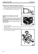
Lower the work equipment to the ground and set the ma-
chine in a stable condition.
4.
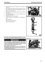
Operate the control grip (g) of the lock lever (1) to set it se-
curely to LOCK position (L) and stop the engine.
5.
Pull out projections (2) (6 places) on the back of the floor
mat and remove the floor mat.
6.
Remove the cap from water drain hole (3).
7.
Flush out the dirt on the floor directly with water through
water drain hole (3).
8.
After completing the washing work, install the cap in water
drain hole (3).
9.
Fit the floor mat and secure it by inserting projections (2)
into the holes.
MAINTENANCE
MAINTENANCE PROCEDURE
4-35
Summary of Contents for PC700LC-11
Page 2: ......
Page 23: ...LOCATION OF SAFETY LABELS 5 SAFETY SAFETY LABELS 2 3...
Page 66: ......
Page 316: ......
Page 396: ......
Page 397: ...SPECIFICATIONS 5 1...
Page 401: ...For 7 6m Boom SPECIFICATIONS SPECIFICATIONS 5 5...
Page 402: ...SPECIFICATIONS SPECIFICATIONS 5 6...
Page 426: ......
Page 427: ...REPLACEMENT PARTS 7 1...
Page 434: ......

