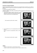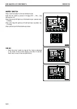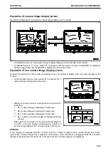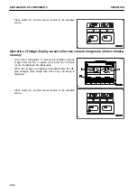
HYDRAULIC OIL TEMPERATURE GAUGE
Hydraulic oil temperature gauge shows the hydraulic oil tem-
perature.
If the indicator is in green range during operation, it is normal.
When the indicator nears the red range (A) during operation,
the hydraulic oil temperature has reached 102 °C or more. Run
the engine at low idle or stop it, and wait for the hydraulic oil
temperature to drop.
(A) to (B): Red range
(A) to (C): Green range
(C) to (D): White range
REMARK
When the indicator reaches the red range (A), the hydraulic oil temperature is as follows.
Red range (A) position: 102 °C or more
Red range (B) position: 105 °C or more
When the indicator is in red range (A) to (B), hydraulic oil temperature caution lamp (E) indicates abnormality.
When the engine is started, if the indicator is at position (C), the hydraulic oil temperature is 20 °C or below and
the hydraulic oil temperature caution lamp (E) indicates low temperature. At this time, perform the warm-up op-
eration.
Display (G) when temperature is low: Caution lamp background
(K) is white.
Display (H) when temperature is correct: Caution lamp back-
ground (K) is blue.
Display (J) when the condition is abnormal: Caution lamp back-
ground (K) is red.
FUEL GAUGE
Fuel gauge shows the amount of fuel in the fuel tank.
The indicator should be in the green range during operations.
When the indicator comes close to the red range (A) during op-
eration, the remaining fuel is 167 ℓ or less, so check and add
fuel.
(A) to (B): Red range
(A) to (C): Green range
REMARK
When the indicator reaches the red range (B), the remaining
fuel is 97 ℓ or less.
When the indicator is in red range (B), the fuel level caution
lamp (D) lights up in red.
The correct fuel level may not be displayed for a short time after the starting switch is turned to ON position, but
this is not a problem.
SERVICE METER / CLOCK
The service meter/clock shows the total hours of operation of the machine or the present time.
When the engine is running, the service meter advances even when the machine is not moving. The service
meter advances 0.1 every 6 operation minutes, regardless of the engine speed.
OPERATION
EXPLANATION OF COMPONENTS
3-37
Summary of Contents for PC700LC-11
Page 2: ......
Page 23: ...LOCATION OF SAFETY LABELS 5 SAFETY SAFETY LABELS 2 3...
Page 66: ......
Page 316: ......
Page 396: ......
Page 397: ...SPECIFICATIONS 5 1...
Page 401: ...For 7 6m Boom SPECIFICATIONS SPECIFICATIONS 5 5...
Page 402: ...SPECIFICATIONS SPECIFICATIONS 5 6...
Page 426: ......
Page 427: ...REPLACEMENT PARTS 7 1...
Page 434: ......


