2.
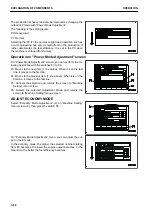
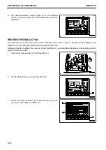
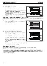
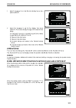
Select the set time on “Auto Idle Stop Timer Setting”
screen shown in the figure, then press the switch F6.
You can perform the following operations with switches F3
to F6 on “Auto Idle Stop Timer Setting” screen.
F3: Moves to the next item (1 line below). When it is on the
last line, it moves to the first line.
F4: Moves to the previous item (1 line above). When it is
on the first line, it moves to the last line.
F5: Cancels the selection and returns the screen to “Ma-
chine Setting” menu screen.
F6: Allocates the selected setting to the Auto Idle Stop Timer Setting.
REMARK
• The auto idle stop function is disabled if you select “OFF”.
• You cannot select a time longer than that specified in the service menu.
3.
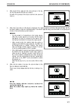
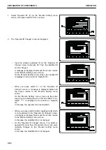
When the idling time reaches 30 seconds before the set
time, the monitor returns to the standard screen, and it
changes to the countdown screen.
When you set the lock lever to FREE position, countdown
stops, and the screen returns to the standard screen.
4.
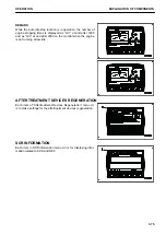
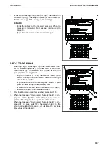
When the countdown reaches 0, the engine stops, and the
screen changes to “Auto Idle Stop in Operation” screen.
5.
Turn off the unnecessary switches to prevent the battery
from discharging.
REMARK
While the auto idle stop is in operation, only the engine
stops. The electrical components including the air condi-
tioner, radio, lamps, and windshield continue to be in oper-
ation as the time before the engine is stopped, and so do
the machine monitor, inverter, etc.
6.
Turn the starting switch to OFF position to prevent the battery from discharging.
7.
Turn the starting switch key as usual to restart the engine.
EXPLANATION OF COMPONENTS
OPERATION
3-74
Summary of Contents for PC700LC-11
Page 2: ......
Page 23: ...LOCATION OF SAFETY LABELS 5 SAFETY SAFETY LABELS 2 3...
Page 66: ......
Page 316: ......
Page 396: ......
Page 397: ...SPECIFICATIONS 5 1...
Page 401: ...For 7 6m Boom SPECIFICATIONS SPECIFICATIONS 5 5...
Page 402: ...SPECIFICATIONS SPECIFICATIONS 5 6...
Page 426: ......
Page 427: ...REPLACEMENT PARTS 7 1...
Page 434: ......

