1.
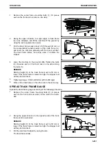
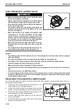
Remove the center frame mounting bolts (1) (16 pieces
each on the front and rear side on one side).
2.
Swing the upper structure to a right angle to track frame
(A) to be retracted, and lift the machine off the ground by
using the work equipment as a jack.
3.
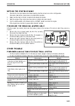
Put the block (B) (wooden block of 20 through 30 cm) at
the comparatively outside position of the track frame (A),
and lower the machine gradually with the boom cylinder.
The track frame slides, and stops when it contacts the
stopper.
4.
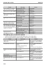
Lower the machine to the ground softly. Tighten the bolts
(2) (8 pieces each on front and rear on one side among
the bolts (1))
REMARK
Raising height (H) of the track frame must be 50 mm or
lower. If the track frame is raised too high, the stopper bolt
will be pried and bent.
5.
Tightening torque: 1960 to 2450 Nm {200 to 250 kgm}
6.
Work on the track frame on the other side in the same way.
SPREAD TRACK FRAME GAUGE
Spread the track frame gauge according to the following procedure.
1.
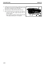
Remove the center frame mounting bolts (2) (8 pieces
each on the front and rear sides) on the side to be exten-
ded.
2.
Swing the upper structure to the opposite side of the track
frame (2) to be extended.
REMARK
Raising height (H) of the track frame must be 50 mm or
lower. If the track frame is raised too high, the stopper bolt
will be pried and bent.
3.
Pull the machine frontward by using the arm.
The track frame slides.
OPERATION
TRANSPORTATION
3-231
Summary of Contents for PC700LC-11
Page 2: ......
Page 23: ...LOCATION OF SAFETY LABELS 5 SAFETY SAFETY LABELS 2 3...
Page 66: ......
Page 316: ......
Page 396: ......
Page 397: ...SPECIFICATIONS 5 1...
Page 401: ...For 7 6m Boom SPECIFICATIONS SPECIFICATIONS 5 5...
Page 402: ...SPECIFICATIONS SPECIFICATIONS 5 6...
Page 426: ......
Page 427: ...REPLACEMENT PARTS 7 1...
Page 434: ......


