


Hydraulic circuit diagram (when swinging to left)90-15
Hydraulic circuit diagram symbol list.....................90-9
Hydraulic circuit diagrams of control valve and names
of valves.....................................................10-144
Hydraulic cylinder circuit - Release remaining pres-
sure..............................................................30-60
Hydraulic oil additional filter (with clogging switch)......
...................................................................10-220
Hydraulic oil additional filter (with clogging switch) -
Specifications.............................................10-220
Hydraulic oil additional filter (with clogging switch) -
Structure.................................................... 10-220
Hydraulic oil additional filter clogging switch.....10-220
Hydraulic oil additional filter clogging switch - Func-
tion............................................................. 10-220
Hydraulic system............................ 10-73,30-60,60-31
Hydraulic system - Layout drawing..................... 10-73
Hydraulic system - Release remaining pressure 30-60
Hydraulic tank................................................... 10-105
Hydraulic tank - Release the remaining pressure........
.....................................................................30-60
Hydraulic tank - Specifications..........................10-105
Hydraulic tank - Structure................................. 10-105
Hydraulic tank breather.....................................10-106
Hydraulic tank breather - Function....................10-106
Hydraulic tank breather - Structure................... 10-106
Hydraulic tank oil filler cap................................ 10-105
Hydraulic tank oil filler cap - Function............... 10-106
Hydraulic tank oil filler cap - Structure.............. 10-105
I
Idler - Maintenance standard.............................. 60-22
Input and output signals of engine controller...... 10-67
Intake system equipment - Precautions for handling...
.....................................................................00-38
Introduction of LS pressure in control valve - Function
...................................................................10-152
K
KOMTRAX setting display (GPS & Communication
Status) - Check.......................................... 30-169
KOMTRAX setting display (Modem Information) -
Confirm...................................................... 30-170
KOMTRAX setting display (Terminal Status) - Confirm
...................................................................30-168
KOMTRAX Settings Menu................................ 30-168
KOMTRAX system..............................................10-45
KOMTRAX system - Function.............................10-45
KOMTRAX system diagram................................10-45
KOMTRAX terminal............................................ 10-58
KOMTRAX terminal - Function........................... 10-59
KOMTRAX terminal - Input and output signals... 10-59
KOMTRAX terminal - Start................................30-173
KOMTRAX terminal - Structure...........................10-58
L
Left front mirror - Adjust.................................... 30-105
Left front mirror (A) - Adjust to the regular position......
...................................................................30-106
LS bypass plug................................................... 10-93
LS bypass plug - Function.................................. 10-94
LS bypass plug of control valve........................ 10-153
LS bypass plug of control valve - Function....... 10-155
LS bypass plug of control valve - Structure...... 10-154
LS differential pressure - Test by using machine mon-
itor................................................................30-80
LS differential pressure - Test with testing tools..30-82
LS pressure in control valve - Operation of introduc-
tion............................................................. 10-153
LS select valve....................................................10-94
LS select valve - Function...................................10-94
LS select valve - Operation.................................10-95
LS select valve of control valve - Function........10-165
LS select valve of control valve - Operation......10-166
LS valve - Adjust................................................. 30-85
LS valve - Function............................................. 10-87
LS valve outlet pressure (servo piston inlet pressure)
- Test............................................................ 30-83
LS-EPC valve outlet pressure - Test................... 30-84
M
Machine - Standard value table.......................... 20-13
Machine monitor................................................. 10-46
Machine monitor - Function................................ 10-46
Machine monitor - Gauges and meters...............10-49
Machine monitor - Operator mode function........ 10-55
Machine monitor - Service mode function...........10-57
Machine monitor - Set/Operate......................... 30-112
Machine monitor - System drawing.....................10-43
Machine monitor - Types of caution lamps displayed..
.....................................................................10-50
Machine monitor - Types of pilot lamps displayed.......
.....................................................................10-53
Machine monitor — Input and output signals......10-47
Machine monitor system..................................... 10-43
Machine monitor system - Function.................... 10-43
Machine posture, Procedure for measuring perform-
ance............................................................. 20-27
Machine push-up - System diagram................. 10-197
Machine push-up system.................................. 10-197
Machine push-up system - Function................. 10-198
Machine rear counterweight mirror (D) - Adjust.30-111
Main pump........................................................ 10-108
Main pump - Function....................................... 10-112
Main pump - Maintenance standard................... 60-31
Main pump - Operation..................................... 10-113
Main pump - Structure...................................... 10-108
Main pump LS -EPC valve................................10-127
Main pump LS -EPC valve - Structure.............. 10-127
Main pump LS valve..........................................10-114
Main pump LS valve - Function.........................10-115
INDEX
4
Summary of Contents for PC500LC-10R
Page 1: ...HYDRAULIC EXCAVATOR SEN06722 00 PC500LC 10R SERIAL NUMBERS 100001 and up...
Page 2: ......
Page 3: ...00 INDEX AND FOREWORD PC500LC 10R 00 1...
Page 76: ......
Page 77: ...01 SPECIFICATIONS PC500LC 10R 01 1...
Page 94: ......
Page 95: ...10 STRUCTURE AND FUNCTION PC500LC 10R 10 1...
Page 177: ...When balanced 10 STRUCTURE AND FUNCTION CLSS PC500LC 10R 10 83...
Page 178: ...When lever is returned to fine control state CLSS 10 STRUCTURE AND FUNCTION 10 84 PC500LC 10R...
Page 179: ...When lever is pulled at a stroke 10 STRUCTURE AND FUNCTION CLSS PC500LC 10R 10 85...
Page 180: ...When lever is in stroke end CLSS 10 STRUCTURE AND FUNCTION 10 86 PC500LC 10R...
Page 377: ...20 STANDARD VALUE TABLE PC500LC 10R 20 1...
Page 407: ...30 TESTING AND ADJUSTING PC500LC 10R 30 1...
Page 583: ...30 TESTING AND ADJUSTING METHOD FOR STARTING UP KOMTRAX TERMINAL PC500LC 10R 30 177...
Page 604: ......
Page 605: ...60 MAINTENANCE STANDARD PC500LC 10R 60 1...
Page 636: ...MAINTENANCE STANDARD OF MAIN PUMP 60 MAINTENANCE STANDARD 60 32 PC500LC 10R...
Page 638: ...MAINTENANCE STANDARD OF SWING MOTOR 60 MAINTENANCE STANDARD 60 34 PC500LC 10R...
Page 641: ...60 MAINTENANCE STANDARD MAINTENANCE STANDARD OF TRAVEL MOTOR PC500LC 10R 60 37...
Page 644: ...MAINTENANCE STANDARD OF CONTROL VALVE 60 MAINTENANCE STANDARD 60 40 PC500LC 10R...
Page 646: ...MAINTENANCE STANDARD OF CONTROL VALVE 60 MAINTENANCE STANDARD 60 42 PC500LC 10R...
Page 648: ...MAINTENANCE STANDARD OF CONTROL VALVE 60 MAINTENANCE STANDARD 60 44 PC500LC 10R...
Page 650: ...MAINTENANCE STANDARD OF CONTROL VALVE 60 MAINTENANCE STANDARD 60 46 PC500LC 10R...
Page 652: ...MAINTENANCE STANDARD OF CONTROL VALVE 60 MAINTENANCE STANDARD 60 48 PC500LC 10R...
Page 658: ...MAINTENANCE STANDARD OF TRAVEL PPC VALVE 60 MAINTENANCE STANDARD 60 54 PC500LC 10R...
Page 668: ...MAINTENANCE STANDARD OF WORK EQUIPMENT LINKAGE 60 MAINTENANCE STANDARD 60 64 PC500LC 10R...
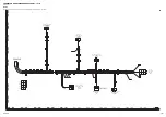
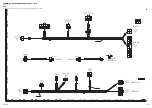
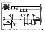
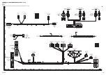
Page 679: ...90 CIRCUIT DIAGRAMS PC500LC 10R 90 1...
Page 692: ......
Page 694: ......
Page 696: ......
Page 698: ......
Page 700: ......
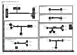
Page 704: ...Symbol Content Buzzer Antenna SYMBOLS USED IN ELECTRICAL CIRCUIT DIAGRAM 90 26 PC500LC 10R...
Page 706: ......
Page 708: ......
Page 710: ......
Page 712: ......
Page 714: ......
Page 716: ......
Page 718: ......
Page 720: ......
Page 722: ......
Page 724: ......
Page 726: ......
Page 728: ......
Page 730: ......
Page 732: ......
Page 734: ......
Page 736: ......
Page 738: ......
Page 740: ......
Page 742: ......
Page 744: ......
Page 746: ......
Page 748: ......
Page 757: ......