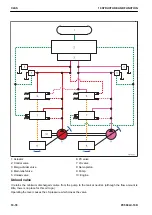


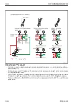


FUNCTION OF PC-EPC VALVE AND LS-EPC VALVE
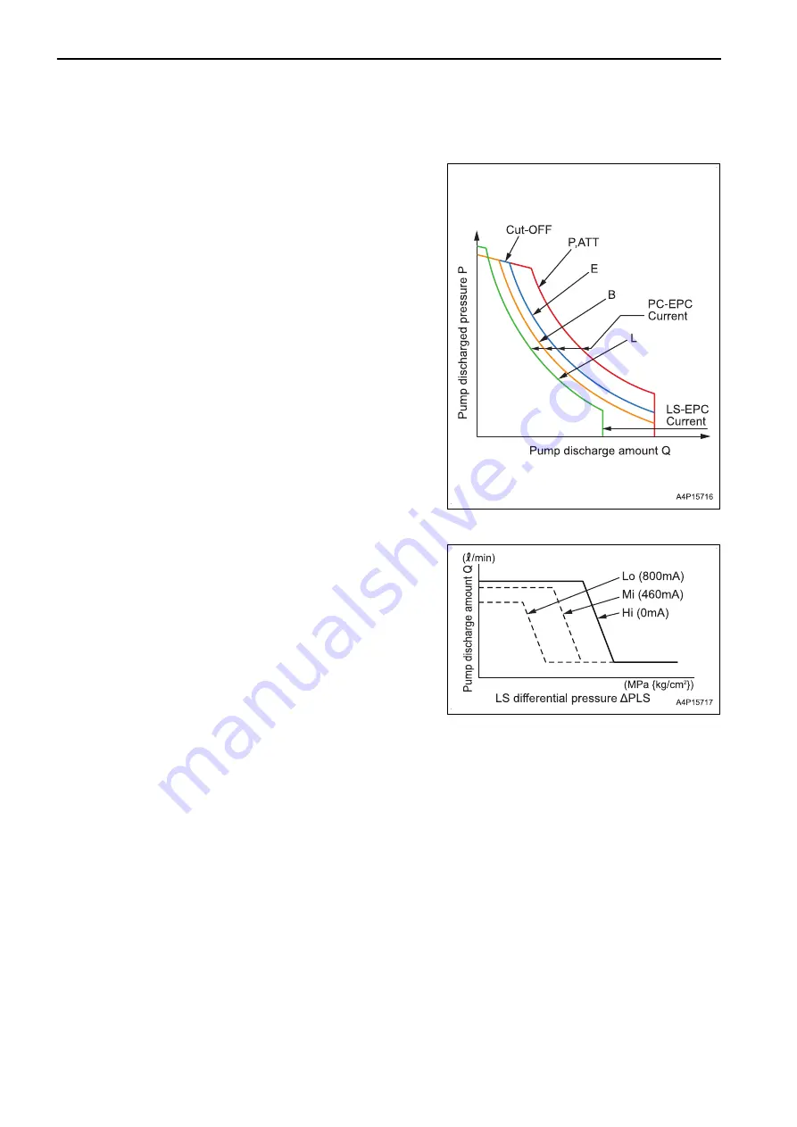
Engine pump control (working mode)
• P,ATT mode hyperbola shows the setting to use maximum
output of engine for hydraulic system, and indicates “Pres-
sure (P) x Discharged volume (Q) = Constant = Engine
output”.
• Command current from the controller to the PC-EPC valve
and LS-EPC valve decreases the pump absorbing horse-
power and maximum pump discharged volume. The com-
mand current increases and the discharged volume de-
creases.
• When E, B or L is selected for the working mode, the set-
tings of engine speed and pump absorbing horsepower
are decreased simultaneously by the controller.
• When the command current is increased and L mode is
selected, LS-EPC valve controls to decrease the maximum
discharged volume.
• When the pressure sensor detects the high pressure close
to the max. set pressure, it is cut off by PC-EPC valve.
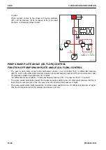
Travel control
• As travel speed selector switch is switched to Hi, Mi or Lo,
command current from controller changes, and the output
pressure from LS-EPC valve to LS valve changes, and
pump discharged volume change point “LS differential
pressure (PLS)” in the LS valve changes.
• The start-up time of the pump discharged volume is opti-
mized and the combined operation and fine control per-
formance are improved.
Cut-off function
• This function increases PC-EPC current to reduce the flow rate in the relief state and improve the fuel econ-
omy.
• Operating condition for turning on cut-off function
When the one-touch power maximizing function is not activated and the average of front pump and rear
pump oil pressure sensor values is 27.9 MPa {285 kg/cm
2
} or higher.
It does not operate when machine is traveling or swing lock switch is “ON”.
CLSS
10 STRUCTURE AND FUNCTION
10-92
PC500LC-10R
Summary of Contents for PC500LC-10R
Page 1: ...HYDRAULIC EXCAVATOR SEN06722 00 PC500LC 10R SERIAL NUMBERS 100001 and up...
Page 2: ......
Page 3: ...00 INDEX AND FOREWORD PC500LC 10R 00 1...
Page 76: ......
Page 77: ...01 SPECIFICATIONS PC500LC 10R 01 1...
Page 94: ......
Page 95: ...10 STRUCTURE AND FUNCTION PC500LC 10R 10 1...
Page 177: ...When balanced 10 STRUCTURE AND FUNCTION CLSS PC500LC 10R 10 83...
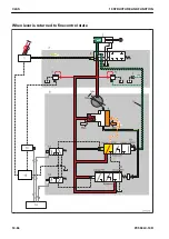
Page 178: ...When lever is returned to fine control state CLSS 10 STRUCTURE AND FUNCTION 10 84 PC500LC 10R...
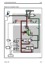
Page 179: ...When lever is pulled at a stroke 10 STRUCTURE AND FUNCTION CLSS PC500LC 10R 10 85...
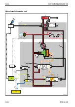
Page 180: ...When lever is in stroke end CLSS 10 STRUCTURE AND FUNCTION 10 86 PC500LC 10R...
Page 377: ...20 STANDARD VALUE TABLE PC500LC 10R 20 1...
Page 407: ...30 TESTING AND ADJUSTING PC500LC 10R 30 1...
Page 583: ...30 TESTING AND ADJUSTING METHOD FOR STARTING UP KOMTRAX TERMINAL PC500LC 10R 30 177...
Page 604: ......
Page 605: ...60 MAINTENANCE STANDARD PC500LC 10R 60 1...
Page 636: ...MAINTENANCE STANDARD OF MAIN PUMP 60 MAINTENANCE STANDARD 60 32 PC500LC 10R...
Page 638: ...MAINTENANCE STANDARD OF SWING MOTOR 60 MAINTENANCE STANDARD 60 34 PC500LC 10R...
Page 641: ...60 MAINTENANCE STANDARD MAINTENANCE STANDARD OF TRAVEL MOTOR PC500LC 10R 60 37...
Page 644: ...MAINTENANCE STANDARD OF CONTROL VALVE 60 MAINTENANCE STANDARD 60 40 PC500LC 10R...
Page 646: ...MAINTENANCE STANDARD OF CONTROL VALVE 60 MAINTENANCE STANDARD 60 42 PC500LC 10R...
Page 648: ...MAINTENANCE STANDARD OF CONTROL VALVE 60 MAINTENANCE STANDARD 60 44 PC500LC 10R...
Page 650: ...MAINTENANCE STANDARD OF CONTROL VALVE 60 MAINTENANCE STANDARD 60 46 PC500LC 10R...
Page 652: ...MAINTENANCE STANDARD OF CONTROL VALVE 60 MAINTENANCE STANDARD 60 48 PC500LC 10R...
Page 658: ...MAINTENANCE STANDARD OF TRAVEL PPC VALVE 60 MAINTENANCE STANDARD 60 54 PC500LC 10R...
Page 668: ...MAINTENANCE STANDARD OF WORK EQUIPMENT LINKAGE 60 MAINTENANCE STANDARD 60 64 PC500LC 10R...
Page 679: ...90 CIRCUIT DIAGRAMS PC500LC 10R 90 1...
Page 692: ......
Page 694: ......
Page 696: ......
Page 698: ......
Page 700: ......
Page 704: ...Symbol Content Buzzer Antenna SYMBOLS USED IN ELECTRICAL CIRCUIT DIAGRAM 90 26 PC500LC 10R...
Page 706: ......
Page 708: ......
Page 710: ......
Page 712: ......
Page 714: ......
Page 716: ......
Page 718: ......
Page 720: ......
Page 722: ......
Page 724: ......
Page 726: ......
Page 728: ......
Page 730: ......
Page 732: ......
Page 734: ......
Page 736: ......
Page 738: ......
Page 740: ......
Page 742: ......
Page 744: ......
Page 746: ......
Page 748: ......
Page 757: ......