


Diodes - Test..................................................... 30-183
Display function of operator identification input screen
................................................................... 30-115
E
Electric circuit diagram symbol list...................... 90-23
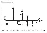
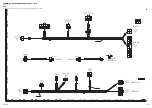
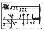
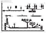
Electrical circuit diagram..................................... 90-23
Electrical circuit diagram (1/7).............................90-27
Electrical circuit diagram (2/7).............................90-29
Electrical circuit diagram (3/7).............................90-31
Electrical circuit diagram (4/7).............................90-33
Electrical circuit diagram (5/7).............................90-35
Electrical circuit diagram (6/7).............................90-37
Electrical circuit diagram (7/7).............................90-39
Engine - Standard value table...............................20-9
Engine - Test oil pressure................................... 30-37
Engine / Cooling system..................................... 30-18
Engine and cooling system................................... 60-9
Engine and plump combined control system...... 10-96
Engine and pump combined control system - Func-
tion.....................................................10-96,10-97
Engine automatic warm-up system.....................10-22
Engine automatic warm-up system - Function....10-23
Engine automatic warm-up system - System diagram.
.....................................................................10-22
Engine control - System diagram........................10-17
Engine control system.........................................10-17
Engine control system - Function........................10-18
Engine controller................................................. 10-66
Engine controller - Structure............................... 10-66
Engine mount - Maintenance standard................. 60-9
Engine oil pressure - Test by machine monitor... 30-37
Engine oil pressure - Test by testing tools.......... 30-37
Engine output control system diagram of fan clutch....
.....................................................................10-37
Engine output control system of fan clutch......... 10-37
Engine output control system of fan clutch - Function.
.....................................................................10-37
Engine speed - Test............................................ 30-18
Engine system.................................................... 10-15
Engine system - Layout drawing.........................10-15
Engine system - Specifications........................... 10-16
EPC valve of 1st-line attachment PPC valve.... 10-210
EPC valve of 1st-line attachment PPC valve - Func-
tion............................................................. 10-212
EPC valve of 1st-line attachment PPC valve - Opera-
tion............................................................. 10-212
EPC valve of 1st-line attachment PPC valve - Struc-
ture.............................................................10-210
Exhaust gas color - Test......................................30-26
Exhaust gas color - Test by handy smoke checker......
.....................................................................30-26
Exhaust gas color - Test by smoke meter........... 30-27
Exhaust gas temperature - Test.......................... 30-24
F
Fan belt - Test..................................................... 30-51
Fan clutch........................................................... 10-39
Fan clutch - Function.......................................... 10-39
Fan clutch - Specification....................................10-39
Fan clutch - Structure..........................................10-39
Fan clutch of fan speed control - System diagram.......
.....................................................................10-35
Fan speed control system of fan clutch.............. 10-35
Fan speed control system of fan clutch - Function ......
.....................................................................10-36
Final drive......................................................... 10-267
Final drive - Function........................................ 10-268
Final drive - Maintenance standard.....................60-15
Final drive - Specifications................................ 10-268
Final drive - Structure........................................10-267
Foreword, Safety, Basic information................... 00-12
Fuel circuit - Test for leakage.............................. 30-47
Fuel circuit - Test leakage................................... 30-47
Fuel control dial...................................................10-70
Fuel control dial - Structure.................................10-70
Fuel feed pump................................................... 10-72
Fuel feed pump - Function.................................. 10-72
Fuel feed pump - Structure................................. 10-72
Fuel pressure - Test............................................ 30-39
Fuel return rate and leakage - Test..................... 30-41
Fuel return rate, fuel leakage - Test.................... 30-41
Fuel system - Bleed air....................................... 30-44
Fuel system equipment - Precautions for handling......
.....................................................................00-37
Function of 2-stage suction-safety valve of control
valve.......................................................... 10-190
Function of 2-stage swing relief valve of swing motor..
...................................................................10-237
Function of arm quick return valve of control valve......
...................................................................10-184
Function of attachment circuit selector valve.... 10-218
Function of auto-deceleration system................. 10-20
Function of CAN terminating resistor.................. 10-66
Function of fuel control dial................................. 10-71
Function of LCD (Liquid Crystal Display) display of
the machine monitor - Check..................... 30-116
Function of service meter - Check.................... 30-117
H
Hi valve of control valve.................................... 10-156
Hi valve of control valve - Function................... 10-156
How to read electrical wire code......................... 00-55
How to read the shop manual............................. 00-12
Hydraulic circuit - Bleed air..................... 30-99,30-101
Hydraulic circuit diagram.......................................90-9
Hydraulic circuit diagram (1/2)............................ 90-19
Hydraulic circuit diagram (2/2)............................ 90-21
Hydraulic circuit diagram (when boom is raised and
upper structure is swung to left)...................90-17
Hydraulic circuit diagram (when boom is raised) 90-13
INDEX
3
Summary of Contents for PC500LC-10R
Page 1: ...HYDRAULIC EXCAVATOR SEN06722 00 PC500LC 10R SERIAL NUMBERS 100001 and up...
Page 2: ......
Page 3: ...00 INDEX AND FOREWORD PC500LC 10R 00 1...
Page 76: ......
Page 77: ...01 SPECIFICATIONS PC500LC 10R 01 1...
Page 94: ......
Page 95: ...10 STRUCTURE AND FUNCTION PC500LC 10R 10 1...
Page 177: ...When balanced 10 STRUCTURE AND FUNCTION CLSS PC500LC 10R 10 83...
Page 178: ...When lever is returned to fine control state CLSS 10 STRUCTURE AND FUNCTION 10 84 PC500LC 10R...
Page 179: ...When lever is pulled at a stroke 10 STRUCTURE AND FUNCTION CLSS PC500LC 10R 10 85...
Page 180: ...When lever is in stroke end CLSS 10 STRUCTURE AND FUNCTION 10 86 PC500LC 10R...
Page 377: ...20 STANDARD VALUE TABLE PC500LC 10R 20 1...
Page 407: ...30 TESTING AND ADJUSTING PC500LC 10R 30 1...
Page 583: ...30 TESTING AND ADJUSTING METHOD FOR STARTING UP KOMTRAX TERMINAL PC500LC 10R 30 177...
Page 604: ......
Page 605: ...60 MAINTENANCE STANDARD PC500LC 10R 60 1...
Page 636: ...MAINTENANCE STANDARD OF MAIN PUMP 60 MAINTENANCE STANDARD 60 32 PC500LC 10R...
Page 638: ...MAINTENANCE STANDARD OF SWING MOTOR 60 MAINTENANCE STANDARD 60 34 PC500LC 10R...
Page 641: ...60 MAINTENANCE STANDARD MAINTENANCE STANDARD OF TRAVEL MOTOR PC500LC 10R 60 37...
Page 644: ...MAINTENANCE STANDARD OF CONTROL VALVE 60 MAINTENANCE STANDARD 60 40 PC500LC 10R...
Page 646: ...MAINTENANCE STANDARD OF CONTROL VALVE 60 MAINTENANCE STANDARD 60 42 PC500LC 10R...
Page 648: ...MAINTENANCE STANDARD OF CONTROL VALVE 60 MAINTENANCE STANDARD 60 44 PC500LC 10R...
Page 650: ...MAINTENANCE STANDARD OF CONTROL VALVE 60 MAINTENANCE STANDARD 60 46 PC500LC 10R...
Page 652: ...MAINTENANCE STANDARD OF CONTROL VALVE 60 MAINTENANCE STANDARD 60 48 PC500LC 10R...
Page 658: ...MAINTENANCE STANDARD OF TRAVEL PPC VALVE 60 MAINTENANCE STANDARD 60 54 PC500LC 10R...
Page 668: ...MAINTENANCE STANDARD OF WORK EQUIPMENT LINKAGE 60 MAINTENANCE STANDARD 60 64 PC500LC 10R...
Page 679: ...90 CIRCUIT DIAGRAMS PC500LC 10R 90 1...
Page 692: ......
Page 694: ......
Page 696: ......
Page 698: ......
Page 700: ......
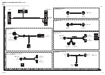
Page 704: ...Symbol Content Buzzer Antenna SYMBOLS USED IN ELECTRICAL CIRCUIT DIAGRAM 90 26 PC500LC 10R...
Page 706: ......
Page 708: ......
Page 710: ......
Page 712: ......
Page 714: ......
Page 716: ......
Page 718: ......
Page 720: ......
Page 722: ......
Page 724: ......
Page 726: ......
Page 728: ......
Page 730: ......
Page 732: ......
Page 734: ......
Page 736: ......
Page 738: ......
Page 740: ......
Page 742: ......
Page 744: ......
Page 746: ......
Page 748: ......
Page 757: ......