


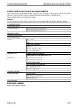


Category
(*1)
Item
Display order (*2)
V
W
X
Y
Z
B
Selection of auto-deceleration
Selection of working mode
Selection of travel speed
Operation of stopping the alarm buzzer
Operation of windshield wiper
Operation of window washer
Operation of air conditioner
Operation to display camera mode
Operation of clock display and service meter display
Check of maintenance information
User menu setting and display
•
Energy Saving Guidance
•
Machine Setting
•
Maintenance
•
Monitor Setting
•
User message (including KOMTRAX messages for user)
C
ECO Guidance display
Caution monitor display
Action level and failure code display
D
Checking function by LCD (liquid crystal display)
Checking function of service meter
Function of usage limitation and changing password
*1: The operator mode items are categorized as follows.
A: Display which is displayed from the time when the starting switch is turned to “ON” position to the time when
display changes to the standard screen, and display which is displayed after starting switch is turned to “OFF”
position
B: Display when the machine monitor switch is operated
C: Display when conditions are satisfied
D: Display that requires special operations of switches
*2: The sequence of display varies with the settings and state of the machine. It shows the sequence from the
time when the starting switch is turned to “ON” position to the time when the standard screen appears.
V: When engine start lock is enabled
W: When engine start lock is disabled
X: When working mode at start is set to “Breaker mode (B)”
Y: When an abnormality is detected by the check before starting
Z: When any item is detected as the maintenance due time is over
REMARK
• For how to operate the operator mode functions, see Operation and Maintenance Manual.
• For the operating method of the engine start lock function, see Password setting and canceling manual.
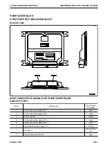
COMPONENT PARTS OF CONTROL SYSTEM
10 STRUCTURE AND FUNCTION
10-56
PC500LC-10R
Summary of Contents for PC500LC-10R
Page 1: ...HYDRAULIC EXCAVATOR SEN06722 00 PC500LC 10R SERIAL NUMBERS 100001 and up...
Page 2: ......
Page 3: ...00 INDEX AND FOREWORD PC500LC 10R 00 1...
Page 76: ......
Page 77: ...01 SPECIFICATIONS PC500LC 10R 01 1...
Page 94: ......
Page 95: ...10 STRUCTURE AND FUNCTION PC500LC 10R 10 1...
Page 177: ...When balanced 10 STRUCTURE AND FUNCTION CLSS PC500LC 10R 10 83...
Page 178: ...When lever is returned to fine control state CLSS 10 STRUCTURE AND FUNCTION 10 84 PC500LC 10R...
Page 179: ...When lever is pulled at a stroke 10 STRUCTURE AND FUNCTION CLSS PC500LC 10R 10 85...
Page 180: ...When lever is in stroke end CLSS 10 STRUCTURE AND FUNCTION 10 86 PC500LC 10R...
Page 377: ...20 STANDARD VALUE TABLE PC500LC 10R 20 1...
Page 407: ...30 TESTING AND ADJUSTING PC500LC 10R 30 1...
Page 583: ...30 TESTING AND ADJUSTING METHOD FOR STARTING UP KOMTRAX TERMINAL PC500LC 10R 30 177...
Page 604: ......
Page 605: ...60 MAINTENANCE STANDARD PC500LC 10R 60 1...
Page 636: ...MAINTENANCE STANDARD OF MAIN PUMP 60 MAINTENANCE STANDARD 60 32 PC500LC 10R...
Page 638: ...MAINTENANCE STANDARD OF SWING MOTOR 60 MAINTENANCE STANDARD 60 34 PC500LC 10R...
Page 641: ...60 MAINTENANCE STANDARD MAINTENANCE STANDARD OF TRAVEL MOTOR PC500LC 10R 60 37...
Page 644: ...MAINTENANCE STANDARD OF CONTROL VALVE 60 MAINTENANCE STANDARD 60 40 PC500LC 10R...
Page 646: ...MAINTENANCE STANDARD OF CONTROL VALVE 60 MAINTENANCE STANDARD 60 42 PC500LC 10R...
Page 648: ...MAINTENANCE STANDARD OF CONTROL VALVE 60 MAINTENANCE STANDARD 60 44 PC500LC 10R...
Page 650: ...MAINTENANCE STANDARD OF CONTROL VALVE 60 MAINTENANCE STANDARD 60 46 PC500LC 10R...
Page 652: ...MAINTENANCE STANDARD OF CONTROL VALVE 60 MAINTENANCE STANDARD 60 48 PC500LC 10R...
Page 658: ...MAINTENANCE STANDARD OF TRAVEL PPC VALVE 60 MAINTENANCE STANDARD 60 54 PC500LC 10R...
Page 668: ...MAINTENANCE STANDARD OF WORK EQUIPMENT LINKAGE 60 MAINTENANCE STANDARD 60 64 PC500LC 10R...
Page 679: ...90 CIRCUIT DIAGRAMS PC500LC 10R 90 1...
Page 692: ......
Page 694: ......
Page 696: ......
Page 698: ......
Page 700: ......
Page 704: ...Symbol Content Buzzer Antenna SYMBOLS USED IN ELECTRICAL CIRCUIT DIAGRAM 90 26 PC500LC 10R...
Page 706: ......
Page 708: ......
Page 710: ......
Page 712: ......
Page 714: ......
Page 716: ......
Page 718: ......
Page 720: ......
Page 722: ......
Page 724: ......
Page 726: ......
Page 728: ......
Page 730: ......
Page 732: ......
Page 734: ......
Page 736: ......
Page 738: ......
Page 740: ......
Page 742: ......
Page 744: ......
Page 746: ......
Page 748: ......
Page 757: ......