


9.
The control valve spool moves to a position at which the pressure in the port (A) which is “equal to the pres-
sure in the port (P1)” is balanced with the reaction force of the return spring of the control valve spool.
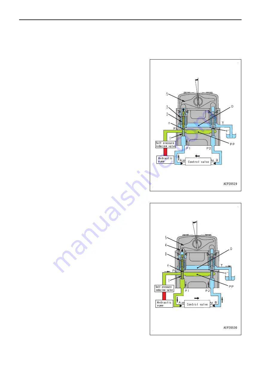
When operating the fine control (when the control lever is returned)
1.
The spool (1) is pushed up by the force of centering spring
(3) and the pressure in port (P1) when lever (5) starts be-
ing returned.
2.
The fine control hole (f) is connected to the drain chamber
(D), and the pressurized oil in the port (P1) is decreased.
3.
The spool (1) is pushed down by the metering spring (2)
when the pressure in the port (P1) decreased too much.
4.
The fine control hole (f) is disconnected from the drain
chamber (D), and it is connected to the pump pressure
chamber (PP) almost simultaneously.
5.
The pump pressure is supplied until the pressure in the
port (P1) is restored to that equivalent at the lever position.
6.
When the spool of control valve returns, the pressurized oil
in the drain chamber (D) flows through fine control hole (f')
in the valve on the side that is not operated. The oil passes
through the port (P2), and it flows to the port (B) to replen-
ish the port with pressurized oil.
When the lever is stroked to the end
1.
The lever (5) pushes down the piston (4), and the retainer
(9) pushes down the spool (1).
2.
The fine control hole (f) is disconnected from the drain
chamber (D) and connected to the pump pressure cham-
ber (PP).
3.
The pilot pressure oil from the self-pressure reducing valve
flows to port (A) through fine control hole (f) and port (P1),
and it pushes the control valve spool.
4.
The oil returning from the port (B) flows from port (P2)
through the fine control hole (f') to the drain chamber (D).
COMPONENT PARTS OF TRAVEL SYSTEM
10 STRUCTURE AND FUNCTION
10-272
PC500LC-10R
Summary of Contents for PC500LC-10R
Page 1: ...HYDRAULIC EXCAVATOR SEN06722 00 PC500LC 10R SERIAL NUMBERS 100001 and up...
Page 2: ......
Page 3: ...00 INDEX AND FOREWORD PC500LC 10R 00 1...
Page 76: ......
Page 77: ...01 SPECIFICATIONS PC500LC 10R 01 1...
Page 94: ......
Page 95: ...10 STRUCTURE AND FUNCTION PC500LC 10R 10 1...
Page 177: ...When balanced 10 STRUCTURE AND FUNCTION CLSS PC500LC 10R 10 83...
Page 178: ...When lever is returned to fine control state CLSS 10 STRUCTURE AND FUNCTION 10 84 PC500LC 10R...
Page 179: ...When lever is pulled at a stroke 10 STRUCTURE AND FUNCTION CLSS PC500LC 10R 10 85...
Page 180: ...When lever is in stroke end CLSS 10 STRUCTURE AND FUNCTION 10 86 PC500LC 10R...
Page 377: ...20 STANDARD VALUE TABLE PC500LC 10R 20 1...
Page 407: ...30 TESTING AND ADJUSTING PC500LC 10R 30 1...
Page 583: ...30 TESTING AND ADJUSTING METHOD FOR STARTING UP KOMTRAX TERMINAL PC500LC 10R 30 177...
Page 604: ......
Page 605: ...60 MAINTENANCE STANDARD PC500LC 10R 60 1...
Page 636: ...MAINTENANCE STANDARD OF MAIN PUMP 60 MAINTENANCE STANDARD 60 32 PC500LC 10R...
Page 638: ...MAINTENANCE STANDARD OF SWING MOTOR 60 MAINTENANCE STANDARD 60 34 PC500LC 10R...
Page 641: ...60 MAINTENANCE STANDARD MAINTENANCE STANDARD OF TRAVEL MOTOR PC500LC 10R 60 37...
Page 644: ...MAINTENANCE STANDARD OF CONTROL VALVE 60 MAINTENANCE STANDARD 60 40 PC500LC 10R...
Page 646: ...MAINTENANCE STANDARD OF CONTROL VALVE 60 MAINTENANCE STANDARD 60 42 PC500LC 10R...
Page 648: ...MAINTENANCE STANDARD OF CONTROL VALVE 60 MAINTENANCE STANDARD 60 44 PC500LC 10R...
Page 650: ...MAINTENANCE STANDARD OF CONTROL VALVE 60 MAINTENANCE STANDARD 60 46 PC500LC 10R...
Page 652: ...MAINTENANCE STANDARD OF CONTROL VALVE 60 MAINTENANCE STANDARD 60 48 PC500LC 10R...
Page 658: ...MAINTENANCE STANDARD OF TRAVEL PPC VALVE 60 MAINTENANCE STANDARD 60 54 PC500LC 10R...
Page 668: ...MAINTENANCE STANDARD OF WORK EQUIPMENT LINKAGE 60 MAINTENANCE STANDARD 60 64 PC500LC 10R...
Page 679: ...90 CIRCUIT DIAGRAMS PC500LC 10R 90 1...
Page 692: ......
Page 694: ......
Page 696: ......
Page 698: ......
Page 700: ......
Page 704: ...Symbol Content Buzzer Antenna SYMBOLS USED IN ELECTRICAL CIRCUIT DIAGRAM 90 26 PC500LC 10R...
Page 706: ......
Page 708: ......
Page 710: ......
Page 712: ......
Page 714: ......
Page 716: ......
Page 718: ......
Page 720: ......
Page 722: ......
Page 724: ......
Page 726: ......
Page 728: ......
Page 730: ......
Page 732: ......
Page 734: ......
Page 736: ......
Page 738: ......
Page 740: ......
Page 742: ......
Page 744: ......
Page 746: ......
Page 748: ......
Page 757: ......