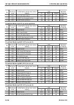


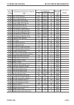
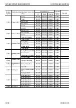


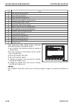


The display unit can be set to “SI”, “Metric”, or “Imperial” as required (Select a desired unit from “Unit” of
“Default” in Service Menu).
The display unit, “mg/st”, is an abbreviation for milligram/stroke.
Unit for display “CA” stands for crankshaft Angle.
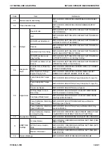
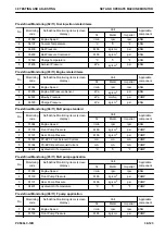
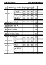
• Applicable component
ENG: The engine controller detects the monitoring information.
PUMP: The pump controller detects the monitoring information.
MON: The machine monitor detects the monitoring information.
*1: “Instantaneous Fuel Consumption” (Code No.: 37300) is the theoretical fuel consumption ratio. (The theoreti-
cal fuel consumption ratio is slightly different from the actual fuel consumption ratio.)
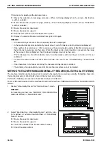
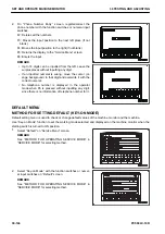
ABNORMALITY RECORD MENU
METHOD FOR CONFIRMING ABNORMALITY RECORD (MECHANICAL SYS-
TEMS)
The machine monitor logs the past and currently occurring failures classifying them into the mechanical system
abnormality and electrical system abnormality.
To check the mechanical system abnormality record, perform the following procedures.
For the failure code list, see “Failure code list”for troubleshooting.
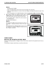
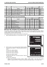
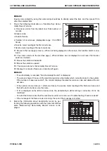
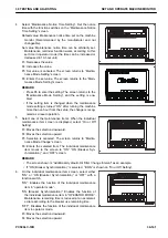
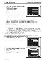
1.
Select “Abnormality Record” on “Service Menu” screen.
REMARK
For selecting method, see “Operating method of service
mode” in “SERVICE MODE”.
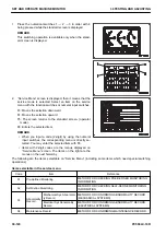
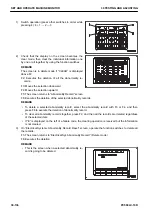
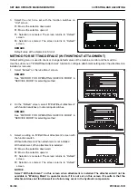
2.
On “Abnormality Record ”screen, select “Mechanical Sys
Abnormality Record” with the function switches or numeral
input switches.
F3: Moves the selection downward
F4: Moves the selection upward
F5: Returns the screen to “Service Menu” screen.
F6: Enters the selection
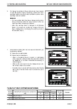
REMARK
Input a code (2-digit) with the numeral input switches to di-
rectly select the item, and then press F6 to enter the selec-
tion.
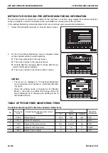
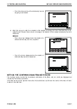
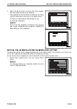
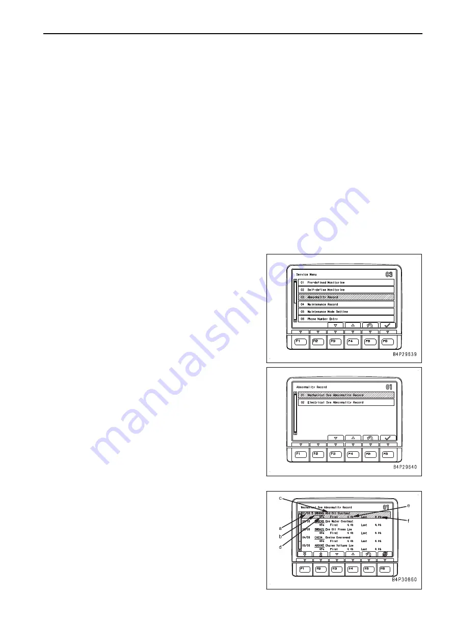
3.
On “Mechanical Sys Abnormality Record” screen, the fol-
lowing information is displayed.
a: Occurrence order of abnormalities from latest one/ Total
number of records
b: Failure code
c: Detail of failure
d: Number of occurrences (displayable range: 0 to 65535
times)
e: Service meter reading at the first occurrence
30 TESTING AND ADJUSTING
SET AND OPERATE MACHINE MONITOR
PC500LC-10R
30-133
Summary of Contents for PC500LC-10R
Page 1: ...HYDRAULIC EXCAVATOR SEN06722 00 PC500LC 10R SERIAL NUMBERS 100001 and up...
Page 2: ......
Page 3: ...00 INDEX AND FOREWORD PC500LC 10R 00 1...
Page 76: ......
Page 77: ...01 SPECIFICATIONS PC500LC 10R 01 1...
Page 94: ......
Page 95: ...10 STRUCTURE AND FUNCTION PC500LC 10R 10 1...
Page 177: ...When balanced 10 STRUCTURE AND FUNCTION CLSS PC500LC 10R 10 83...
Page 178: ...When lever is returned to fine control state CLSS 10 STRUCTURE AND FUNCTION 10 84 PC500LC 10R...
Page 179: ...When lever is pulled at a stroke 10 STRUCTURE AND FUNCTION CLSS PC500LC 10R 10 85...
Page 180: ...When lever is in stroke end CLSS 10 STRUCTURE AND FUNCTION 10 86 PC500LC 10R...
Page 377: ...20 STANDARD VALUE TABLE PC500LC 10R 20 1...
Page 407: ...30 TESTING AND ADJUSTING PC500LC 10R 30 1...
Page 583: ...30 TESTING AND ADJUSTING METHOD FOR STARTING UP KOMTRAX TERMINAL PC500LC 10R 30 177...
Page 604: ......
Page 605: ...60 MAINTENANCE STANDARD PC500LC 10R 60 1...
Page 636: ...MAINTENANCE STANDARD OF MAIN PUMP 60 MAINTENANCE STANDARD 60 32 PC500LC 10R...
Page 638: ...MAINTENANCE STANDARD OF SWING MOTOR 60 MAINTENANCE STANDARD 60 34 PC500LC 10R...
Page 641: ...60 MAINTENANCE STANDARD MAINTENANCE STANDARD OF TRAVEL MOTOR PC500LC 10R 60 37...
Page 644: ...MAINTENANCE STANDARD OF CONTROL VALVE 60 MAINTENANCE STANDARD 60 40 PC500LC 10R...
Page 646: ...MAINTENANCE STANDARD OF CONTROL VALVE 60 MAINTENANCE STANDARD 60 42 PC500LC 10R...
Page 648: ...MAINTENANCE STANDARD OF CONTROL VALVE 60 MAINTENANCE STANDARD 60 44 PC500LC 10R...
Page 650: ...MAINTENANCE STANDARD OF CONTROL VALVE 60 MAINTENANCE STANDARD 60 46 PC500LC 10R...
Page 652: ...MAINTENANCE STANDARD OF CONTROL VALVE 60 MAINTENANCE STANDARD 60 48 PC500LC 10R...
Page 658: ...MAINTENANCE STANDARD OF TRAVEL PPC VALVE 60 MAINTENANCE STANDARD 60 54 PC500LC 10R...
Page 668: ...MAINTENANCE STANDARD OF WORK EQUIPMENT LINKAGE 60 MAINTENANCE STANDARD 60 64 PC500LC 10R...
Page 679: ...90 CIRCUIT DIAGRAMS PC500LC 10R 90 1...
Page 692: ......
Page 694: ......
Page 696: ......
Page 698: ......
Page 700: ......
Page 704: ...Symbol Content Buzzer Antenna SYMBOLS USED IN ELECTRICAL CIRCUIT DIAGRAM 90 26 PC500LC 10R...
Page 706: ......
Page 708: ......
Page 710: ......
Page 712: ......
Page 714: ......
Page 716: ......
Page 718: ......
Page 720: ......
Page 722: ......
Page 724: ......
Page 726: ......
Page 728: ......
Page 730: ......
Page 732: ......
Page 734: ......
Page 736: ......
Page 738: ......
Page 740: ......
Page 742: ......
Page 744: ......
Page 746: ......
Page 748: ......
Page 757: ......