


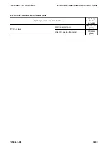

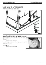

TEST PPC VALVE OUTLET PRESSURE
Testing tools for PPC valve output pressure
Symbol
Part No.
Part name
Q'ty
Remarks
A
-
799-101-5002
Hydraulic tester
1
1
799-101-5130
Gauge
1
Pressure range: 6 MPa
2
799-101-5160
Nipple
1
Size: R1/8
B
790-261-1205
Digital hydraulic tester
1
Pressure range: 70 MPa
C
790-301-1730
Joint
1
Size: PF1/4 x Rc1/8
D
07000-12011
O-ring
1
k
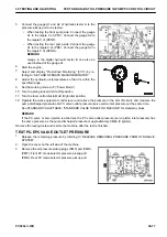
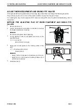
Lower the work equipment to the ground, and stop the engine. Operate the control lever several
times to release the remaining pressure in the piping. Loosen the oil filler cap of the hydraulic tank
gradually to release the pressure in the tank.
Test this item under the following conditions.
Hydraulic oil temperature : 45 to 55 °C
Before testing this item, check that the control circuit oil pressure is normal.
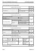
You can check the following PPC valve outlet pressure with the monitoring function of the machine monitor (For
details, see “SETTING AND OPERATION OF MACHINE MONITOR”).
Monitoring code: 07400“Boom Raise PPC Pressure”
Monitoring code: 07500“Boom Lower PPC Pressure”
Monitoring code: 07200“Arm IN PPC Pressure”
Monitoring code: 07600“Arm OUT PPC Pressure”
Monitoring code: 07300“Bucket CURL PPC Pressure”
Monitoring code: 07301“Bucket DUMP PPC Pressure”
Monitoring code: 09001“Swing Left PPC Pressure”
Monitoring code: 09002“Swing Right PPC Pressure”
Monitoring code: 07102“Travel Forward Left PPC Press”
Monitoring code: 07103“Travel Forward Right PPC Press”
Monitoring code: 07104“Travel Reverse Left PPC Press”
Monitoring code: 07105“Travel Reverse Right PPC Press”
For testing and adjusting of PPC valve output pressure to perform troubleshooting or Pm Clinic, etc. refer to this
section.
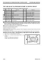
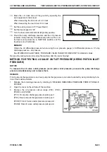
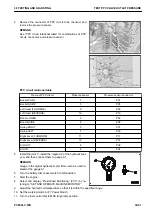
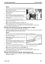
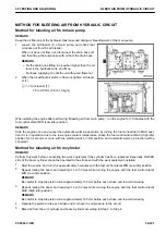
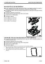
METHOD FOR TESTING PPC VALVE OUTLET PRESSURE
1.
Release the remaining pressure by referring to “RELEASE REMAINING PRESSURE FROM HYDRAULIC
SYSTEM”.
2.
Check that the system operating lamp is not lit, and turn the battery disconnect switch to OFF position.
3.
Remove the undercover (1).
TEST PPC VALVE OUTLET PRESSURE
30 TESTING AND ADJUSTING
30-90
PC500LC-10R
Summary of Contents for PC500LC-10R
Page 1: ...HYDRAULIC EXCAVATOR SEN06722 00 PC500LC 10R SERIAL NUMBERS 100001 and up...
Page 2: ......
Page 3: ...00 INDEX AND FOREWORD PC500LC 10R 00 1...
Page 76: ......
Page 77: ...01 SPECIFICATIONS PC500LC 10R 01 1...
Page 94: ......
Page 95: ...10 STRUCTURE AND FUNCTION PC500LC 10R 10 1...
Page 177: ...When balanced 10 STRUCTURE AND FUNCTION CLSS PC500LC 10R 10 83...
Page 178: ...When lever is returned to fine control state CLSS 10 STRUCTURE AND FUNCTION 10 84 PC500LC 10R...
Page 179: ...When lever is pulled at a stroke 10 STRUCTURE AND FUNCTION CLSS PC500LC 10R 10 85...
Page 180: ...When lever is in stroke end CLSS 10 STRUCTURE AND FUNCTION 10 86 PC500LC 10R...
Page 377: ...20 STANDARD VALUE TABLE PC500LC 10R 20 1...
Page 407: ...30 TESTING AND ADJUSTING PC500LC 10R 30 1...
Page 583: ...30 TESTING AND ADJUSTING METHOD FOR STARTING UP KOMTRAX TERMINAL PC500LC 10R 30 177...
Page 604: ......
Page 605: ...60 MAINTENANCE STANDARD PC500LC 10R 60 1...
Page 636: ...MAINTENANCE STANDARD OF MAIN PUMP 60 MAINTENANCE STANDARD 60 32 PC500LC 10R...
Page 638: ...MAINTENANCE STANDARD OF SWING MOTOR 60 MAINTENANCE STANDARD 60 34 PC500LC 10R...
Page 641: ...60 MAINTENANCE STANDARD MAINTENANCE STANDARD OF TRAVEL MOTOR PC500LC 10R 60 37...
Page 644: ...MAINTENANCE STANDARD OF CONTROL VALVE 60 MAINTENANCE STANDARD 60 40 PC500LC 10R...
Page 646: ...MAINTENANCE STANDARD OF CONTROL VALVE 60 MAINTENANCE STANDARD 60 42 PC500LC 10R...
Page 648: ...MAINTENANCE STANDARD OF CONTROL VALVE 60 MAINTENANCE STANDARD 60 44 PC500LC 10R...
Page 650: ...MAINTENANCE STANDARD OF CONTROL VALVE 60 MAINTENANCE STANDARD 60 46 PC500LC 10R...
Page 652: ...MAINTENANCE STANDARD OF CONTROL VALVE 60 MAINTENANCE STANDARD 60 48 PC500LC 10R...
Page 658: ...MAINTENANCE STANDARD OF TRAVEL PPC VALVE 60 MAINTENANCE STANDARD 60 54 PC500LC 10R...
Page 668: ...MAINTENANCE STANDARD OF WORK EQUIPMENT LINKAGE 60 MAINTENANCE STANDARD 60 64 PC500LC 10R...
Page 679: ...90 CIRCUIT DIAGRAMS PC500LC 10R 90 1...
Page 692: ......
Page 694: ......
Page 696: ......
Page 698: ......
Page 700: ......
Page 704: ...Symbol Content Buzzer Antenna SYMBOLS USED IN ELECTRICAL CIRCUIT DIAGRAM 90 26 PC500LC 10R...
Page 706: ......
Page 708: ......
Page 710: ......
Page 712: ......
Page 714: ......
Page 716: ......
Page 718: ......
Page 720: ......
Page 722: ......
Page 724: ......
Page 726: ......
Page 728: ......
Page 730: ......
Page 732: ......
Page 734: ......
Page 736: ......
Page 738: ......
Page 740: ......
Page 742: ......
Page 744: ......
Page 746: ......
Page 748: ......
Page 757: ......