


Remove the testing tools and restore the machine after the test
is finished.
Install the injector, injector wiring harness, and fuel high-pres-
sure tube according to the following procedure.
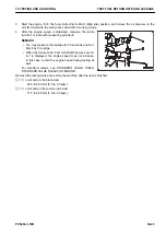
1.
Install the O-rings (8), (9), and gasket (10) to injector (5).
2.
Fit the holder (11) to injector (5) to temporarily assemble
them as a unit to the cylinder head.
3.
Fit spherical washer (13) to mounting bolt (12) and tighten
them to the cylinder head.
2
Spherical part of washer:
Engine oil (SAE30DH)
3
Mounting bolt:
58.8 to 73.5 Nm {6.0 to 7.5 kgm}
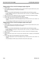
4.
Insert the harness (14) into the rocker arm housing, and fix it with the mounting bolt (15).
5.
Insert the wiring harness (14) into holder (16).
6.
Alternately tighten 2 nuts at the end of wiring harness (14) to injector (5).
3
Nut:
2.0 to 2.4 Nm {0.2 to 0.24 kgm}
7.
Tighten the tube (17) to injector (5).
3
Sleeve nut:
39.2 to 49.0 Nm {4 to 5 kgm}
8.
Tighten the clamping bolt of the fuel piping.
3
Clamp bolt:
11.8 to 14.7 Nm {1.2 to 1.5 kgm}
3
Rocker arm assembly mounting bolt:
58.8 to 73.5 Nm {6.0 to 7.5 kgm}
9.
Adjust the valve clearance by referring to the “TEST AND ADJUST VALVE CLEARANCE”.
3
Cylinder head cover mounting bolt:
9.8±1 Nm {1.0±0.1 kgm}
30 TESTING AND ADJUSTING
TEST COMPRESSION PRESSURE
PC500LC-10R
30-33
Summary of Contents for PC500LC-10R
Page 1: ...HYDRAULIC EXCAVATOR SEN06722 00 PC500LC 10R SERIAL NUMBERS 100001 and up...
Page 2: ......
Page 3: ...00 INDEX AND FOREWORD PC500LC 10R 00 1...
Page 76: ......
Page 77: ...01 SPECIFICATIONS PC500LC 10R 01 1...
Page 94: ......
Page 95: ...10 STRUCTURE AND FUNCTION PC500LC 10R 10 1...
Page 177: ...When balanced 10 STRUCTURE AND FUNCTION CLSS PC500LC 10R 10 83...
Page 178: ...When lever is returned to fine control state CLSS 10 STRUCTURE AND FUNCTION 10 84 PC500LC 10R...
Page 179: ...When lever is pulled at a stroke 10 STRUCTURE AND FUNCTION CLSS PC500LC 10R 10 85...
Page 180: ...When lever is in stroke end CLSS 10 STRUCTURE AND FUNCTION 10 86 PC500LC 10R...
Page 377: ...20 STANDARD VALUE TABLE PC500LC 10R 20 1...
Page 407: ...30 TESTING AND ADJUSTING PC500LC 10R 30 1...
Page 583: ...30 TESTING AND ADJUSTING METHOD FOR STARTING UP KOMTRAX TERMINAL PC500LC 10R 30 177...
Page 604: ......
Page 605: ...60 MAINTENANCE STANDARD PC500LC 10R 60 1...
Page 636: ...MAINTENANCE STANDARD OF MAIN PUMP 60 MAINTENANCE STANDARD 60 32 PC500LC 10R...
Page 638: ...MAINTENANCE STANDARD OF SWING MOTOR 60 MAINTENANCE STANDARD 60 34 PC500LC 10R...
Page 641: ...60 MAINTENANCE STANDARD MAINTENANCE STANDARD OF TRAVEL MOTOR PC500LC 10R 60 37...
Page 644: ...MAINTENANCE STANDARD OF CONTROL VALVE 60 MAINTENANCE STANDARD 60 40 PC500LC 10R...
Page 646: ...MAINTENANCE STANDARD OF CONTROL VALVE 60 MAINTENANCE STANDARD 60 42 PC500LC 10R...
Page 648: ...MAINTENANCE STANDARD OF CONTROL VALVE 60 MAINTENANCE STANDARD 60 44 PC500LC 10R...
Page 650: ...MAINTENANCE STANDARD OF CONTROL VALVE 60 MAINTENANCE STANDARD 60 46 PC500LC 10R...
Page 652: ...MAINTENANCE STANDARD OF CONTROL VALVE 60 MAINTENANCE STANDARD 60 48 PC500LC 10R...
Page 658: ...MAINTENANCE STANDARD OF TRAVEL PPC VALVE 60 MAINTENANCE STANDARD 60 54 PC500LC 10R...
Page 668: ...MAINTENANCE STANDARD OF WORK EQUIPMENT LINKAGE 60 MAINTENANCE STANDARD 60 64 PC500LC 10R...
Page 679: ...90 CIRCUIT DIAGRAMS PC500LC 10R 90 1...
Page 692: ......
Page 694: ......
Page 696: ......
Page 698: ......
Page 700: ......
Page 704: ...Symbol Content Buzzer Antenna SYMBOLS USED IN ELECTRICAL CIRCUIT DIAGRAM 90 26 PC500LC 10R...
Page 706: ......
Page 708: ......
Page 710: ......
Page 712: ......
Page 714: ......
Page 716: ......
Page 718: ......
Page 720: ......
Page 722: ......
Page 724: ......
Page 726: ......
Page 728: ......
Page 730: ......
Page 732: ......
Page 734: ......
Page 736: ......
Page 738: ......
Page 740: ......
Page 742: ......
Page 744: ......
Page 746: ......
Page 748: ......
Page 757: ......