

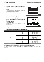

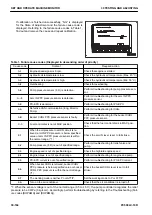

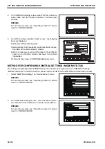

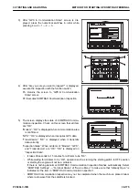
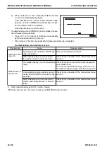

If calibration is finished unsuccessfully, “NG” is displayed
for the State of Adjustment and the failure cause code is
displayed. Referring to the failure cause codes in Table 1,
find out and remove the cause and repeat calibration.
Table 1. Failure cause codes (Displayed in descending order of priority)
Cause code
Content
Required action
A-1
Engine speed signal is 0 rpm.
Check that engine is started.
A-2
Hydraulic oil temperature is low.
Check the hydraulic oil temperature (Max. 45 °C)
A-3
Hydraulic oil temperature is high.
Check the hydraulic oil temperature (Min. 55 °C)
A-4
Overheating
Check for overheating
A-6
Pump pressure sensor (F, R) is defective.
Perform troubleshooting for pump pressure sen-
sor.
A—8
Arm IN PPC pressure sensor is defective.
Perform troubleshooting for the arm IN PPC
pressure sensor
A-9
PC-EPC is abnormal.
Perform troubleshooting for PC-EPC.
A-A
Defective CAN communication (Eng, Monitor,
Pump)
Perform troubleshooting for CAN.
A-B
Bucket CURL PPC pressure sensor is faulty.
Perform troubleshooting for the bucket CURL
PPC pressure sensor.
C-3
Fuel control dial is not at MAX position.
Check that the fuel control dial is in MAX posi-
tion.
E-1
When the oil pressure in arm IN circuit is re-
lieved, arm IN PPC pressure is below specified
value or arm IN PPC pressure sensor is within
the normal range. (*1)
Check the arm IN lever is set to full stroke.
E-2
Pump pressure (F, R) is out of specified range.
Perform troubleshooting for relief valve and
pump.
E-3
Engine speed is out of specified range.
Check the high idle engine speed
E-4
Engine torque is out of specified range.
Perform troubleshooting for engine and pump.
E-5
PC-EPC current is out of specified range.
Perform troubleshooting for PC-EPC current.
E-6
When bucket CURL is relieved, bucket CURL
PPC pressure is below specified value or bucket
CURL PPC pressure is within the normal range.
(*1)
Check the bucket CURL lever is set to full
stroke.
E-7
The working mode is neither P nor ATT/P.
Set the working mode to P or ATT/P.
E-A
Turn on the air conditioner.
Check that the air conditioner is turned off.
*1: When the sensor voltage is out of the normal range (0.5 to 4.5 V), the pump controller recognizes the relief
pressure to be 0 MPa {0 kg/cm
2
} . Accordingly, perform troubleshooting by referring to the Troubleshooting (Fail-
ure codes [DHPAMA] and [DHPBMA]).
SET AND OPERATE MACHINE MONITOR
30 TESTING AND ADJUSTING
30-164
PC500LC-10R
Summary of Contents for PC500LC-10R
Page 1: ...HYDRAULIC EXCAVATOR SEN06722 00 PC500LC 10R SERIAL NUMBERS 100001 and up...
Page 2: ......
Page 3: ...00 INDEX AND FOREWORD PC500LC 10R 00 1...
Page 76: ......
Page 77: ...01 SPECIFICATIONS PC500LC 10R 01 1...
Page 94: ......
Page 95: ...10 STRUCTURE AND FUNCTION PC500LC 10R 10 1...
Page 177: ...When balanced 10 STRUCTURE AND FUNCTION CLSS PC500LC 10R 10 83...
Page 178: ...When lever is returned to fine control state CLSS 10 STRUCTURE AND FUNCTION 10 84 PC500LC 10R...
Page 179: ...When lever is pulled at a stroke 10 STRUCTURE AND FUNCTION CLSS PC500LC 10R 10 85...
Page 180: ...When lever is in stroke end CLSS 10 STRUCTURE AND FUNCTION 10 86 PC500LC 10R...
Page 377: ...20 STANDARD VALUE TABLE PC500LC 10R 20 1...
Page 407: ...30 TESTING AND ADJUSTING PC500LC 10R 30 1...
Page 583: ...30 TESTING AND ADJUSTING METHOD FOR STARTING UP KOMTRAX TERMINAL PC500LC 10R 30 177...
Page 604: ......
Page 605: ...60 MAINTENANCE STANDARD PC500LC 10R 60 1...
Page 636: ...MAINTENANCE STANDARD OF MAIN PUMP 60 MAINTENANCE STANDARD 60 32 PC500LC 10R...
Page 638: ...MAINTENANCE STANDARD OF SWING MOTOR 60 MAINTENANCE STANDARD 60 34 PC500LC 10R...
Page 641: ...60 MAINTENANCE STANDARD MAINTENANCE STANDARD OF TRAVEL MOTOR PC500LC 10R 60 37...
Page 644: ...MAINTENANCE STANDARD OF CONTROL VALVE 60 MAINTENANCE STANDARD 60 40 PC500LC 10R...
Page 646: ...MAINTENANCE STANDARD OF CONTROL VALVE 60 MAINTENANCE STANDARD 60 42 PC500LC 10R...
Page 648: ...MAINTENANCE STANDARD OF CONTROL VALVE 60 MAINTENANCE STANDARD 60 44 PC500LC 10R...
Page 650: ...MAINTENANCE STANDARD OF CONTROL VALVE 60 MAINTENANCE STANDARD 60 46 PC500LC 10R...
Page 652: ...MAINTENANCE STANDARD OF CONTROL VALVE 60 MAINTENANCE STANDARD 60 48 PC500LC 10R...
Page 658: ...MAINTENANCE STANDARD OF TRAVEL PPC VALVE 60 MAINTENANCE STANDARD 60 54 PC500LC 10R...
Page 668: ...MAINTENANCE STANDARD OF WORK EQUIPMENT LINKAGE 60 MAINTENANCE STANDARD 60 64 PC500LC 10R...
Page 679: ...90 CIRCUIT DIAGRAMS PC500LC 10R 90 1...
Page 692: ......
Page 694: ......
Page 696: ......
Page 698: ......
Page 700: ......
Page 704: ...Symbol Content Buzzer Antenna SYMBOLS USED IN ELECTRICAL CIRCUIT DIAGRAM 90 26 PC500LC 10R...
Page 706: ......
Page 708: ......
Page 710: ......
Page 712: ......
Page 714: ......
Page 716: ......
Page 718: ......
Page 720: ......
Page 722: ......
Page 724: ......
Page 726: ......
Page 728: ......
Page 730: ......
Page 732: ......
Page 734: ......
Page 736: ......
Page 738: ......
Page 740: ......
Page 742: ......
Page 744: ......
Page 746: ......
Page 748: ......
Page 757: ......