


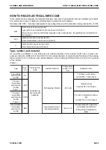


HOW TO READ ELECTRICAL WIRE CODE
In the electrical circuit diagram, the material, thickness, and color of each electric wire are indicated by symbols.
The electrical wire code is helpful in understanding the electrical circuit diagram.
Example) AEX 0.85 L: Indicates heat-resistant, low-voltage blue wire for automobile, having nominal No. of 0.85
AEX
Indicates type of wire by symbol.
Type, symbol, and material of wire are shown in (Table 1).
(Since the use of AV and AVS wires depends on size (nominal No.), the symbols are not indicated on
the diagram.)
0.85
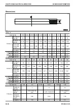
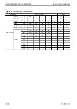
Indicates size of wire by nominal No.
Sizes (Nominal Nos.) are shown in (Table 2).
L
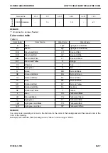
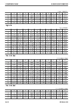
Indicates color of wire by color code.
Color codes are shown in (Table 3).
Type, symbol, and material
AV and AVS are different in only thickness and outside diameter of the coating. CAVS has a circular com-
pressed conductor. It differs from AV and AVS in the outside diameter of conductor and thickness of the coating.
AEX is similar to AV in thickness and outside diameter of the coating but different from AV and AVS in material
of the coating.
(Table 1)
Type
Sym-
bol
Conductor ma-
terial
Insulator material
Temperature
range (°C) in
use
Example of use
Low-voltage
wire for auto-
mobile
AV
Annealed cop-
per for electric
appliance
Soft polyvinyl chloride
-30 to +60
For large current wiring
(nominal No. 5 and above)
Thin-cover
low-voltage
wire for auto-
mobile
(Type 1)
AVS
General wiring
(nominal No. 3 and lower)
Thin-cover
low-voltage
wire for auto-
mobile
(Type 2)
CAVS
For mid- to small-size excava-
tors
(nominal No. 1.25 and lower)
Heat-resistant
low-voltage
wire for auto-
mobile
AEX
Heat-resistant cross-
linked polyethylene
-50 to +110
General wiring for extremely
cold weather specification
Wiring at high-temperature
place
00 INDEX AND FOREWORD
HOW TO READ ELECTRICAL WIRE CODE
PC500LC-10R
00-55
Summary of Contents for PC500LC-10R
Page 1: ...HYDRAULIC EXCAVATOR SEN06722 00 PC500LC 10R SERIAL NUMBERS 100001 and up...
Page 2: ......
Page 3: ...00 INDEX AND FOREWORD PC500LC 10R 00 1...
Page 76: ......
Page 77: ...01 SPECIFICATIONS PC500LC 10R 01 1...
Page 94: ......
Page 95: ...10 STRUCTURE AND FUNCTION PC500LC 10R 10 1...
Page 177: ...When balanced 10 STRUCTURE AND FUNCTION CLSS PC500LC 10R 10 83...
Page 178: ...When lever is returned to fine control state CLSS 10 STRUCTURE AND FUNCTION 10 84 PC500LC 10R...
Page 179: ...When lever is pulled at a stroke 10 STRUCTURE AND FUNCTION CLSS PC500LC 10R 10 85...
Page 180: ...When lever is in stroke end CLSS 10 STRUCTURE AND FUNCTION 10 86 PC500LC 10R...
Page 377: ...20 STANDARD VALUE TABLE PC500LC 10R 20 1...
Page 407: ...30 TESTING AND ADJUSTING PC500LC 10R 30 1...
Page 583: ...30 TESTING AND ADJUSTING METHOD FOR STARTING UP KOMTRAX TERMINAL PC500LC 10R 30 177...
Page 604: ......
Page 605: ...60 MAINTENANCE STANDARD PC500LC 10R 60 1...
Page 636: ...MAINTENANCE STANDARD OF MAIN PUMP 60 MAINTENANCE STANDARD 60 32 PC500LC 10R...
Page 638: ...MAINTENANCE STANDARD OF SWING MOTOR 60 MAINTENANCE STANDARD 60 34 PC500LC 10R...
Page 641: ...60 MAINTENANCE STANDARD MAINTENANCE STANDARD OF TRAVEL MOTOR PC500LC 10R 60 37...
Page 644: ...MAINTENANCE STANDARD OF CONTROL VALVE 60 MAINTENANCE STANDARD 60 40 PC500LC 10R...
Page 646: ...MAINTENANCE STANDARD OF CONTROL VALVE 60 MAINTENANCE STANDARD 60 42 PC500LC 10R...
Page 648: ...MAINTENANCE STANDARD OF CONTROL VALVE 60 MAINTENANCE STANDARD 60 44 PC500LC 10R...
Page 650: ...MAINTENANCE STANDARD OF CONTROL VALVE 60 MAINTENANCE STANDARD 60 46 PC500LC 10R...
Page 652: ...MAINTENANCE STANDARD OF CONTROL VALVE 60 MAINTENANCE STANDARD 60 48 PC500LC 10R...
Page 658: ...MAINTENANCE STANDARD OF TRAVEL PPC VALVE 60 MAINTENANCE STANDARD 60 54 PC500LC 10R...
Page 668: ...MAINTENANCE STANDARD OF WORK EQUIPMENT LINKAGE 60 MAINTENANCE STANDARD 60 64 PC500LC 10R...
Page 679: ...90 CIRCUIT DIAGRAMS PC500LC 10R 90 1...
Page 692: ......
Page 694: ......
Page 696: ......
Page 698: ......
Page 700: ......
Page 704: ...Symbol Content Buzzer Antenna SYMBOLS USED IN ELECTRICAL CIRCUIT DIAGRAM 90 26 PC500LC 10R...
Page 706: ......
Page 708: ......
Page 710: ......
Page 712: ......
Page 714: ......
Page 716: ......
Page 718: ......
Page 720: ......
Page 722: ......
Page 724: ......
Page 726: ......
Page 728: ......
Page 730: ......
Page 732: ......
Page 734: ......
Page 736: ......
Page 738: ......
Page 740: ......
Page 742: ......
Page 744: ......
Page 746: ......
Page 748: ......
Page 757: ......