background image

MAINTENANCE

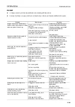
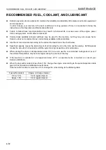
RECOMMENDED FUEL, COOLANT, AND LUBRICANT

4-13

USE OF FUEL, COOLANT AND LUBRICANTS ACCORDING TO AMBIENT 
TEMPERATURE

4

Reservoir

Fluid type

AMBIENT 

TEMPERATURE

Recommended komatsu Fluids

Min

Max

Engine oil pan

Engine oil

-30°C

30°C

SAE0W30EOS and HTHS 3.5min. 
(Note.1)
Komatsu EOS0W30

-25°C

40°C

SAE5W40EOS and HTHS 3.5min. 
(Note.1)
Komatsu EOS5W40

-20°C

40°C

SAE10W30DH
Komatsu EO10W30DH

-15°C

50°C

SAE15W40DH
Komatsu EO15W40DH

0°C

40°C

SAE30DH
Komatsu EO30DH

Damper case
Idler (each)

Power train oil
 (note 2)

-30°C

50° C

TO30

Power train case

Power train oil 

-30°C

0° C

10° C

50°C

TO10
TO30

Final drive case (each)

Power train oil 

-30°C

50°C

TO30

Hydraulic system

Power train oil 

-20° C

40° C

TO10

Hydraulic oil

-20° C

45° C

HO46-HM

Engine oil

-20° C

50° C

SAE10W30DH
Komatsu EO10W30DH

-15° C

50° C

SAE15W40DH
Komatsu EO15W40DH

Grease fitting

Hyper grease
(Note. 3)

-20° C

50° C

G2-T, G2-TE

Lithium EP grease

-20° C

50° C

G2-LI

Cooling sytem

Supercoolant
 AF-NAC

-30°C

50°C

AF-NAC (Note. 4)

Fuel tank

Diesel fuel

0° C

-30° C

50° C
20° C

ASTM No. 2-D
ASTM No. 1-D

Engine oil 

pan

Damper 

case

Power train 

case

Final drive 

case 

(each)

Hydraulic sys-

tem

(With blade,

without ripper)

Cooling sys-

tem

(including 

sub-tank)

Fuel tank

Specified 

capacity

Liters

42

1.5

90

58

126

107

625

Refill 

capacity

Liters

37

1.5

45

58

87

-

-

Summary of Contents for 76243

Page 1: ...y or death Operators and maintenance personnel must read this manual before operating or maintaining this machine This manual should be kept inside the cab for reference and periodically reviewed by all personnel who will come into contact with the machine Operation Maintenance Manual EEAM023402 WARNING ...

Page 2: ......

Page 3: ...FOREWORD 11 ...

Page 4: ...understand them fully Keep this manual in the storage location for the operation and maintenance manual given below and have all personnel read it periodically If this manual has been lost or has become dirty and cannot be read request a replacement manual imme diately from Komatsu or your Komatsu distributor If you sell the machine be sure to give this manual to the new owners together with the m...

Page 5: ...FOREWORD FOREWORD 1 3 q Machine equipped without cab Back pocket of operator s seat ...

Page 6: ...identally touch the control levers when they are not locked this may cause a serious injury or death Other signal words In addition to the above the following signal words are used to indicate precautions that should be followed to pro tect the machine or to give information that is useful to know Indicates an imminently hazardous situation which if not avoided will result in death or serious inju...

Page 7: ...side a triangle and the method of avoiding the hazardous condition is shown inside a circle Komatsu cannot predict every circumstance that might involve a potential hazard in operation and maintenance Therefore the safety messages in this manual and on the machine may not include all possible safety precau tions If any procedures or actions not specifically recommended or allowed in this manual ar...

Page 8: ...s of vibration for the earth moving machine transmitted from the opera tor s seat are lower than or equal to the tested vibrations for the relative machinery class in compliance with ISO 7096 The actual acceleration value for the hands and arms is less than or equal to 2 5 m s The actual acceleration value for the body is less than or equal to 0 5 m s These values were determined using a represent...

Page 9: ...ned and adjusted q Adjust the seat and suspension for the weight and size of the operator q Wear seat belt q Inspect and maintain the seat suspension and adjustment mechanisms 5 Steer brake accelerate shift gears for wheeled machines and move the attachment levers and pedals slowly so that the machine moves smoothly 6 Adjust the machine speed and travel path to minimize the vibration level q When ...

Page 10: ... q Pushing q Ripping For further details see WORK POSSIBLE USING BULLDOZER 3 118 and RIPPER OPERATION 3 111 FRONT REAR LEFT RIGHT DIRECTIONS OF MACHINE 1 In this manual the terms front rear left and right refer to the travel direction as seen from the operator s seat when the operator s seat is facing the front and the sprocket is at the rear of the machine Front Right Sprocket Operator s seat Lef...

Page 11: ...urs as indicated on the service meter Make sure that you fully understand the content of this manual and pay careful attention to the following points when breaking in the machine q Run the engine at idling for 15 seconds after starting it During this time do not operate the control levers or fuel control dial q Idle the engine for 5 minutes after starting it up q Avoid operation with heavy loads ...

Page 12: ...llowing items PRODUCT IDENTIFICATION NUMBER PIN MACHINE SERIAL NO PLATE 1 Under the front of the console box on the right side of the operator s seat The design of the nameplate differs according to the territory ENGINE SERIAL NO PLATE AND POSITION 1 1 q On the upper of the engine starting motor on the right side of the machine q This also acts as the EPA plate ...

Page 13: ... same content as engine serial No plate 1 q Located on the top of the air cleaner mounting bracket on the left of the machine q This also acts as the EPA plate EPA Environmental Protection Agency U S A BLADE SERIAL NO PLATE POSITION 1 This is located on the upper right of blade back surface ...

Page 14: ...ORD 1 12 RIPPER SERIAL NO PLATE POSITION 1 This is located on the left side surface of ripper beam ROPS FOPS NO PLATE POSITION 1 This is located on the top left POSITION OF SERVICE METER 1 On top of the machine monitor ROPS FOPS ...

Page 15: ...E Machine serial No Engine serial No Product Identification Number Manufacturers name Address KOMATSU LTD 3 6 Akasaka Minato ku 101 Tokyo Japan Distributor Address Phone Service personnel for your machine Model Seriel Number Manufacturing year Weight Engine power Product Identification Number Manufacturer ...

Page 16: ...NECESSARY INFORMATION FOREWORD 1 14 ...

Page 17: ...FOREWORD NECESSARY INFORMATION 1 15 ...

Page 18: ...IAL NO PLATE AND POSITION 1 1 10 ENGINE SERIAL NO PLATE AND POSITION 2 1 11 BLADE SERIAL NO PLATE POSITION 1 11 RIPPER SERIAL NO PLATE POSITION 1 12 ROPS FOPS NO PLATE POSITION 1 12 POSITION OF SERVICE METER 1 12 TABLE TO ENTER SERIAL NO AND DISTRIBUTOR 1 13 MACHINE SERIAL NUMBER PLATE 1 13 SAFETY SAFETY 2 2 SAFETY LABELS 2 4 POSITIONS OF SAFETY PICTOGRAMS 2 4 SAFETY LABELS 2 5 GENERAL PRECAUTIONS...

Page 19: ...DIO HANDLING 3 50 EXPLANATION OF COMPONENTS 3 50 METHOD OF USE 3 52 PRECAUTIONS WHEN USING 3 54 CAR STEREO HANDLING 3 55 EXPLANATION OF COMPONENTS 3 55 METHOD OF OPERATION 3 58 PRECAUTION WHEN USING 3 60 AIR CONDITIONER 3 61 GENERAL LOCATIONS AND FUNCTION OF CONTROL PANEL 3 61 METHOD OF OPERATION 3 63 PRECAUTIONS WHEN USING 3 64 SET SO THAT COLD AIR DOES NOT DIRECTLY BLOW ONTO THE GLASS SURFACE 3 ...

Page 20: ...GES 3 106 PERMISSIBLE WATER DEPTH 3 106 PRECAUTIONS WHEN TRAVELING UP OR DOWN HILLS 3 106 PRECAUTIONS ON SLOPE 3 107 METHOD OF USING BRAKES 3 107 PROHIBITED TO KEEP THE DOOR OPEN DURING OPERATIONS 3 107 IT IS PROHIBITED TO MODIFY THE CAB GLASS IN ANY WAY THAT WILL OBSTRUCT THE VIEW 3 107 PRECAUTIONS FOR BLIND SPOTS CAUSED BY CAB STAY AND ROPS STAY 3 108 PARKING MACHINE 3 108 CHECK AFTER STOPPING E...

Page 21: ...FTING MACHINE 3 131 PRECAUTIONS FOR TRANSPORTATION 3 132 TRAVELING ON ROADS 3 132 REMOVAL OF CAB 3 133 COLD WEATHER OPERATION 3 135 PRECAUTIONS FOR LOW TEMPERATURE 3 135 FUEL AND LUBRICANTS 3 135 COOLANT 3 135 BATTERY 3 136 AFTER COMPLETION OF WORK 3 136 AFTER COLD WEATHER 3 137 LONG TERM STORAGE 3 138 BEFORE STORAGE 3 138 DURING STORAGE 3 138 AFTER STORAGE 3 138 TROUBLESHOOTING 3 139 AFTER RUNNIN...

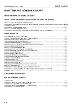
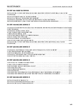
Page 22: ...AN KOMATSU GENUINE OIL 4 14 STANDARD TIGHTENING TORQUES FOR BOLTS AND NUTS 4 15 TORQUE LIST 4 15 PERIODIC REPLACEMENT OF SAFETY CRITICAL PARTS 4 16 SAFETY CRITICAL PARTS 4 16 MAINTENANCE SCHEDULE CHART 4 18 MAINTENANCE SCHEDULE CHART 4 18 INITIAL 250 HOURS SERVICE ONLY AFTER THE FIRST 250 HOURS 4 18 WHEN REQUIRED 4 18 CHECK BEFORE STARTING 4 18 EVERY 250 HOURS SERVICE 4 18 EVERY 500 HOURS SERVICE ...

Page 23: ...AL PRECAUTIONS 6 2 PRECAUTIONS RELATED TO SAFETY 6 2 INTRODUCTION OF ATTACHMENTS AND OPTIONS 6 3 INTRODUCTION OF ATTACHMENTS AND OPTIONS 6 3 HEADREST HANDLING 6 4 CAP WITH LOCK HANDLING 6 5 METHOD OF OPENING AND CLOSING CAP WITH LOCK 6 5 PROCEDURE FOR SELECTING RIPPER POINT 6 6 PROCEDURE FOR SELECTING RIPPER POINT 6 6 INDEX COLOPHON ...

Page 24: ...CONTENTS 1 22 ...

Page 25: ...G Please be sure that you fully understand this manual and the precautions discribed in this manual and the safety labels on the machine When operating or servicing the machine always follow these precaustions strictly ...

Page 26: ...Leaving Operator s Seat 2 132 Handrails and Steps 2 132 Mounting and Dismounting 2 142 No People on Attachments 2 142 Prevention of Burns 2 142 Fire Prevention 2 152 Action if Fire Occurs 2 162 Window Washer Liquid 2 162 Precautions when Using ROPS 2 162 Precautions for Attachments 2 172 Unauthorized Modification 2 172 Safety at Worksite 2 172 Working on Loose Ground 2 172 Do not Go Close to High ...

Page 27: ...Warning Tag 2 302 Keep Work Place Clean and Tidy 2 302 Appoint Leader when Working with Others 2 302 Stop Engine Before Carrying Out Inspection and Maintenance 2 312 Two Workers for Maintenance when Engine is Running 2 322 Proper Tools 2 322 Handling Accumulator 2 332 Personnel 2 332 Attachments 2 332 Work Under the Machine 2 332 Noise 2 342 Precautions when Using Hammer 2 342 Repair Welding 2 342...

Page 28: ...SAFETY LABELS SAFETY 2 4 SAFETY LABELS 2 POSITIONS OF SAFETY PICTOGRAMS 2 ...

Page 29: ...se spotter if view is obstructed Follow above even if the machine is equipped with back up alarm and mirrors 3 Warning for leaving operator s seat 09654 B0641 q Sign indicates a hazard of unexpected moving of stopped machine q Lower working device to ground move safety lever to lock position and take engine key with you before leaving machine To prevent SEVERE INJURY or DEATH do the following befo...

Page 30: ...s a hazzard of flying plug from track adjuster that could cause injury q Read the manual and adjusting track for safe and proper handling 6 Precautions for handling accumulator 09659 A057B q There is the hazard of explotion causing injury q Do not disassemble the accumulator make holes in it weld it cut it hit it roll it or bring it near flame 7 Precautions for use of seat belt 195 98 12940 CAUTIO...

Page 31: ...d maintenance manual and carrying out the correct method when handling 9 Caution against falling 09805 C0881 q Sign indicates a hazard of falling q Do not stand on this place here 10 Caution to stop engine when carrying out inspection and maintenance 09667 A0481 q Sign indicates a hazard of rotating parts such as belt q Turn off before inspection and maintenance ...

Page 32: ... is a danger of electrocution Turn the starting switch OFF before starting inspection or repairs and read the operation and maintenance manual WARNING Electrical hazard Switch off the key Read manual before servicing 13 Jump start prohibited 09842 A0481 q Start the engine only after sitting down in the operator s seat q Do not attempt to start the engine by short circuiting the engine starting cir...

Page 33: ...WARNING q If some modification is applied to the ROPS It might not enough strength and might not be complied with the standard Consult Komatsu Distributor before altering q ROPS may provide less protection if it has been structurally damaged or involved roll over Consult Komatsu Distributor in that case q Always wear seat belt when moving 1 2 3 4 5 1 MODEL 3 FOPS LEVEL No 5 MAX MASS kg Lb 2 MACHIN...

Page 34: ...s applied to the FOBS It might not enough strength and might not be complied with the standard Consult Komatsu Distributor before altering q FOBS may provide less protection if it has been structurally damaged or involved roll over Consult Komatsu Distributor in that case q Always wear seat belt when moving 1 2 3 4 1 MODEL 2 MACHINE MODEL 3 SERIAL NO 4 FOPS LEVEL No ...

Page 35: ...achine until the problem has been corrected CLOTHING AND PERSONAL PROTECTIVE ITEMS q Do not wear loose clothing and accessories There is a hazard that they may catch on control levers or other protruding parts q If you have long hair and it hangs out from your hard hat there is a hazard that it may get caught up in the machine so tie your hair up and be careful not to let it get caught q Always we...

Page 36: ...he machine is still dirty with mud or oil there is a hazard that you will slip and fall or that dirt or mud will get into your eyes Always keep the machine clean INSIDE OPERATOR S COMPARTMENT q When entering the operator s compartment always remove all mud and oil from the soles of your shoes If you operate the pedal with mud or oil affixed to your shoes your foot may slip and this may cause a ser...

Page 37: ...ver and parking lever securely to the LOCK position then stop the engine Use the key to lock all the equipment Always remove the key take it with you and keep it in the specified place HANDRAILS AND STEPS To prevent personal injury caused by slipping or falling off the machine always do as follows q Use the parts marked by arrow A in the diagrams when getting on or off the machine Never use the pa...

Page 38: ...ver get on or off a moving machine q If the machine starts to move when there is no operator on the machine do not jump on to the machine and try to stop it NO PEOPLE ON ATTACHMENTS Never let anyone ride on the work equipment or other attachments There is a hazard of falling and suffering seri ous injury PREVENTION OF BURNS Hot coolant q To prevent burns from hot water or steam spurting out when c...

Page 39: ...use a non flammable oil Diesel oil and gasoline may catch fire so do not use them q Put greasy rags and other flammable materials into a safe container to maintain safety at the work place q Do not weld or use a cutting torch to cut any pipes or tubes that contain flammable liquids q Fire coming from accumulated flammable materials Remove any flammable materials such as dry leaves chips pieces of ...

Page 40: ...he handrails and steps to get off the machine WINDOW WASHER LIQUID Use an ethyl alcohol base washer liquid Methyl alcohol base washer liquid may irritate your eyes so do not use it PRECAUTIONS WHEN USING ROPS Roll Over Protective Structure Install ROPS when working in places where there is danger of falling rocks such as in mines and quarries or in places where there is danger of rolling over q If...

Page 41: ...safest method of operation Do not carry out operations at places where there is a hazard of landslides or falling rocks q If water lines gas lines or high voltage electrical lines may be buried under the worksite contact each utility and iden tify their locations Be careful not to sever or damage any of these lines q Take necessary measures to prevent any unauthorized person from entering the oper...

Page 42: ...e close to the machine q If the machine should come too close or touch the electric cable to prevent electric shock the operator should not leave the operator s compartment until it has been confirmed that the electricity has been shut off Also do not let anyone come close to the machine ENSURE GOOD VISIBILITY q Check for any persons or obstacles in the area around the machine and check the condit...

Page 43: ...ncer if it is inhaled There is danger of inhaling asbestos when working on jobsites handling demolition work or work handling industrial waste Always observe the following q Spray water to keep down the dust when cleaning Do not use compressed air for cleaning q If there is danger that there may be asbestos dust in the air always operate the machine from an upwind position All workers should use a...

Page 44: ...just the operator s seat to a position where it is easy to carry out operations and check that there is no dam age or wear to the seat belt or mounting clamps q Check that the gauges work properly check the angle of the lights and working lamps and check that the con trol levers are all in the neutral position q Adjust the mirrors so that you can get a good rear view from the operator s seat For t...

Page 45: ...ne will be slow and this may lead to unexpected accidents q If the battery electrolyte is frozen do not charge the battery or start the engine with a different power source There is a hazard that this will ignite the battery and cause the battery to explode Before charging or starting the engine with a different power source melt the battery electrolyte and check that there is no leakage of electr...

Page 46: ...of oil or fuel q If any problem is found carry out repairs immediately PRECAUTIONS FOR MOVING MACHINE FORWARD OR IN REVERSE q Before travelling check again that there is no one in the surrounding area and that there are no obstacles q Before travelling sound the horn to warn people in the area q Always operate the machine only when seated q Do not allow anyone apart from the operator to ride on th...

Page 47: ... the machine tilt strongly to one side q When traveling or carrying out operations always keep a safe distance from people structures or other machines to avoid coming into contact with them q When passing over bridges or structures check first that the structure is strong enough to support the weight of the machine When traveling on public roads check first with the relevant authorities and follo...

Page 48: ...d etc to prevent rolling of the machine caused by an overload and disasters caused by break age of the work equipment USING BRAKES q When the machine is traveling do not rest your foot on the brake pedal If you travel with your foot resting on the pedal the brake will always be applied and this will cause the brakes to overheat and fail q Do not depress the brake pedal repeatedly if not necessary ...

Page 49: ...aining pressure in the hydraulic circuit q When parking the machine on a road put up flags fences lighting or warning signs to enable passing vehi cles to recognize the machine clearly At the same time make sure that these do not cause obstruction to the passing vehicles Procedure for parking See PARKING MACHINE 3 108 q When leaving the machine set the lock levers for work equipment and brake to t...

Page 50: ... The weight transportation height and overall length of the machine differ according to the work equipment so be sure to confirm the dimensions q When passing over bridges or structures on private land check first that the structure is strong enough to sup port the weight of the machine When traveling on public roads check first with the relevant authorities and fol low their instructions q For de...

Page 51: ...king with batteries turn the starting switch to the OFF position As there is a hazard that sparks will be generated always do as follows q Do not let tools or other metal objects make any contact between the battery terminals Do not leave tools or other metal objects lying around near the battery q Always disconnect the negative terminal ground side first when removing the battery when installing ...

Page 52: ...blem machine There is a hazard that the machine will move when the power is connected q Be sure to connect the positive cable first when install ing the booster cables Disconnect the negative cable ground side first when removing them q When removing the booster cables be careful not to let the booster cable clips touch each other or to let the clips touch the machine q Always wear safety goggles ...

Page 53: ...opes is dangerous When doing so choose a gentle slope If no gentle slope is available make such a slope by earth removal work q When connecting up a towing machine do not let anyone enter the area between the towing machine and the equip ment being towed q Do not straddle the towing cable or wire rope q When your machine is towed by another machine ALWAYS use a wire rope with a sufficient towing c...

Page 54: ...he work equipment control lever while you are performing service or maintenance you could suffer serious injury or property damage KEEP WORK PLACE CLEAN AND TIDY q Do not leave hammers or other tools lying around in the work place Wipe up all grease oil or other sub stances that will cause you to slip Always keep the work place clean and tidy to enable you to carry out oper ations safely If the wo...

Page 55: ...r landslides or of flooding if the land is low q Lower the work equipment completely to the ground and stop the engine q Operate the blade control lever 2 3 times to the RAISE and LOWER positions to release the remaining pressure in the hydraulic circuit then set work equipment lock lever to the LOCK position q Put blocks under the track to prevent the machine from moving Lock Free Lock Free Block...

Page 56: ...to the LOCK position to prevent the machine from moving q When carrying out operations near the fan fan belt or other rotating parts there is a hazard of being caught in the parts so be careful not to come close q Do not touch any control levers If any control lever must be operated give a signal to the other workers to warn them to move to a safe place q Never drop or insert tools or other object...

Page 57: ...as from the accumulator A special air bleed valve is necessary for this operation please contact your Komatsu distributor PERSONNEL Only authorized personnel can service and repair the machine Do not allow unauthorized personnel into the area If necessary employ an observer ATTACHMENTS q Appoint a leader before starting removal or installation operations for attachments q Place attachments that ha...

Page 58: ... pin hit with strong force may fly out and injure people in the surrounding area REPAIR WELDING Welding operations must always be carried out by a qualified welder and in a place equipped with proper equip ment There is a hazard of gas fire or electrocution when carrying out welding so never allow any unqualified personnel to carry out welding REMOVING BATTERY TERMINAL When repairing the electrica...

Page 59: ... wear safety glasses and leather gloves q There is a hazard that high pressure oil leaking from small holes may penetrate your skin or cause blindness if it con tacts your eyes directly If you are hit by a jet of high pres sure oil and suffer injury to your skin or eyes wash the place with clean water and consult a doctor immediately for medical attention PRECAUTION FOR HIGH FUEL PRESSURE High pre...

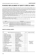
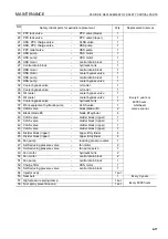
Page 60: ...COMPRESSED AIR q When carrying out cleaning with compressed air there is a hazard of serious injury caused by flying particles q When using compressed air to clean elements or the radiator always wear safety goggles dust mask gloves and other protective equipment PERIODIC REPLACEMENT OF SAFETY CRITICAL PARTS q In order for the machine to be operated safety for a long time it is necessary to add oi...

Page 61: ...OPERATION 13 WARNING Please read and make sure that you understand the SAFETY section before reading this section ...

Page 62: ...N 3 2 GENERAL VIEW 3 GENERAL VIEW OF MACHINE 3 1 Blade 7 Multi ripper 2 Blade tilt cylinder 8 Ripper lift cylinder 3 Blade lift cylinder 9 Sprocket 4 Cab 10 Track frame 5 Track shoe 11 Frame 6 Ripper tilt cylinder 12 Idler ...

Page 63: ...Brake pedal 5 Joystick Steering directional and gear shift lever 15 Deceleration pedal 16 Blade control lever 6 Auto shift down switch 17 Horn switch 7 Front lamp switch 18 Ripper control lever 8 Air conditioner panel or heater panel speed range display engine speed 19 Ripper control lever 20 Pin puller control switch if equipped 9 Rear lamp switch 21 Wiper switch 10 Fan rotation selector switch 2...

Page 64: ...rning lampFilter oil change interval lamp 4 Fuel level gauge 13 Filter oil change interval lamp 5 Charge level caution lamp 14 Display panel A speed range display engine speed 6 Engine oil pressure caution lamp 7 Engine coolant temperature caution lamp 15 Display panel B multi information 8 Power train oil temperature caution lamp 16 Fan operation confirmation lamp 9 Hydraulic oil temperature caut...

Page 65: ...tor group see CHECK MONITOR GROUP 3 7 Before the engine is started the basic items among the check before starting items that must be checked are dis played If there is any abnormality the caution lamp for the location of the abnormality flashes NOTICE When performing the check before starting do not rely only on these monitors Always perform the inspection items according to the maintenance secti...

Page 66: ...idling and take the following action This displays the abnormal items that action must be taken on immediately the engine is running If there is any abnormality the monitor showing the location of the abnormality will flash and the alarm buzzer will sound D Meter group see METER GROUP 3 14 This consists of the preheating pilot lamp power train oil temperature gauge engine water temperature gauge h...

Page 67: ...not light contact your Komatsu distributor to inspect and repair REMARK When the starting switch is turned to the ON position before starting the engine the caution lamps flash for 2 sec onds the warning lamps light up for 2 seconds and the alarm buzzer sounds for 2 seconds The caution lamps cannot be checked for any malfunction until at least 5 seconds after the engine has been stopped This displ...

Page 68: ...ATION 3 8 MAINTENANCE CAUTION LAMP This lamp 1 flashes when the time for changing the filter or oil has been exceeded DISPLAY PANEL B Multi information 3 16 to the maintenance mode and check or replace the appropriate filter or oil ...

Page 69: ...nfirm that monitor lamps light up about 2 seconds after the starting switch is turned to the ON posi tion If any monitor lamp does not light contact your Komatsu distributor to inspect and repair These are items which need to be observed when the engine is running If any problem occurs the item needing immediate repair is displayed If there is any problem the problem location on the caution lamp w...

Page 70: ... while the engine is running If the monitor lamp flashes check the V belt tension If any abnormality is found see OTHER TROUBLE 3 146 REMARK This monitor lamp lights when the starting switch is turned to ON immediately after the engine is started or immediately before the engine is stopped It does not indicate an problem ...

Page 71: ... turned to ON If any monitor lamp does not light have your Komatsu distributor inspect and repair it These items need to be observed while the engine is running If any abnormality occurs items that need to be repaired immediately are displayed If there is any abnormality alarm buzzer sounds intermittently and the abnormal location on the caution lamp will flash C 1 Engine oil pressure caution lamp...

Page 72: ...olant temperature When the monitor lamp flashes run the engine at low idling speed until green range of the engine coolant temperature gauge lights POWER TRAIN OIL TEMPERATURE CAUTION LAMP This lamp 3 indicates a rise in the oil temperature of the torque converter outlet When the monitor lamp flashes run the engine at the low idling speed until the green range of the power train oil temperature ga...

Page 73: ... monitor 5 warns the operator that the HSS charge pres sure has dropped If it flashes stop the engine and carry out inspection REMARK The buzzer may sound when the starting switch is turned ON or immediately after the engine is started but this does not indi cate any abnormality ...

Page 74: ...fuel control dial to lower engine speed to approx 3 4 of the full speed and run until the coolant temperature enters green range B During operation if red range C lights up the engine coolant temperature monitor flashes and the alarm buzzer sounds stop the machine run the engine at low idling and wait for the coolant temperature to go down to green range B A White range B Green range C Red range N...

Page 75: ... that you lower the speed range by one range in order to reduce the load on the power train during operations HYDRAULIC OIL TEMPERATURE GAUGE Gauge 3 indicates the hydraulic oil temperature If the temperature is normal during operation green range B will light If the red range C lights up during operation move the fuel control lever to lower the engine speed to approx 3 4 of the full speed reduce ...

Page 76: ...n the top and bottom lines of the display portion The content of the display can be switched by operating the Information switch and Buzzer cancel switch 1 Operating mode normal operation screen Use this mode when operating the machine REMARK When the starting switch is turned from the OFF to the ON position the multi information display changes to the operating mode The bottom right of the monito...

Page 77: ...N OF COMPONENTS 3 17 2 Maintenance mode The maintenance mode is displayed by continuing to turn the information switch in the direction for 2 5 seconds For details see METHOD OF USING DISPLAY PANEL B Multi information 3 23 ...

Page 78: ...vice circuits activate Keep key in the ON position after starting START In this key position the starting motor will crank the engine Immediately after starting the engine release the key which will automatically return to the ON position E 1 Starting switch E 5 Rear lamp switch E 2 Buzzer cancel switch E 6 Fan rotation selector switch E 3 Information switch E 7 Auto shift down switch E 4 Front la...

Page 79: ...e information monitor and to move the cursor in the maintenance mode Position a Cursor moves to left mode item display goes back to previous item Position b Cursor moves to right mode item display advances to next item FRONT LAMP SWITCH This switch 4 is used to light up the front lamp Position a OFF Lamp goes out Position b ON Lamp lights up REMARK When the head lamp switch is turned ON the monito...

Page 80: ... the fan rotation selector switch turn the starting switch to the ON position but do not start the engine q After the engine is started even if the fan rotation selector switch is operated the fan operation confirmation lamp will flash to inform the operator that the switching operation cannot be carried out AUTO SHIFT DOWN SWITCH When this switch 7 is operated to the right if the load condi tions...

Page 81: ...int When the caution lamp for the B CAUTION or C CAUTION groups flashes and an abnormality is detected by the electronic control system the alarm buzzer sounds and this lamp 1 flashes at the same time If the lamp flashes use the monitor panel to check for the loca tion of the abnormality F 1 Warning lamp F 3 Fan operation confirmation lamp F 2 Filter oil change interval lamp ...

Page 82: ...tor switch is operated this lamp will flash to inform the operator that the switching operation cannot be carried out q Before the engine is started if the starting switch is turned ON and the fan rotation selector switch is set to the reverse mode REV position or clean mode CLN POSI TION lamp 3 will light up to inform the operator that the mode has been set to reverse mode REV or clean mode CLN A...

Page 83: ...formation switch 2 and buzzer cancel switch 3 on the dashboard in front of the operator s seat After operating the switch if the switch is released it will automatically return to the center position as shown in the diagram on the right The functions for each position of the switches are as fol lows Mode item display goes back to previous item cursor moves to left Mode item display advances to nex...

Page 84: ...code display mode position Go to maintenance mode position Go to normal operation screen position Go to PM clinic auxiliary mode selection item screen 3 The diagram on the right shows the screen display for the fault code display mode Use the controls to change the mode as follows position Go to adjustment mode position Go to PM clinic auxiliary mode position Go to normal operation screen position...

Page 85: ... has been replaced select the applicable item then operate the buzzer cancel switch to The screen will ask if you want to display the replacement his tory Operate the information switch to select YES then operate the buzzer cancel switch to The replacement account will increase by 1 the replacement interval will be reset and the oil filter change interval lamp will go out When this is done if the ...

Page 86: ...EXPLANATION OF COMPONENTS OPERATION 3 26 REMARK To return to the function selection mode operate the buzzer cancel switch to ...

Page 87: ...d by operating the information switch REMARK Sometimes when measuring with the engine running the display may flicker and be difficult to read In such cases switch the buzzer cancel switch to The value at that moment is shown on the fixed display To cancel this mode operate the buzzer cancel switch once more to To return to each function selection mode operate the buzzer cancel switch to The displ...

Page 88: ...is detected the location and fault code are displayed by a 6 digit code on display panel B When contacting your Komatsu distributor inform your distributor of the code at the same time If the failure observation function has not determined the condi tion of the machine the display is as shown in the diagram on the right With this function existing failures can be displayed up to a maximum of 20 it...

Page 89: ...panel On this screen operate the buzzer cancel switch to to switch to the screen to adjust the brightness The brightness can be adjusted by operating the information switch The higher the number the brighter the screen becomes the lower the number the darker the screen becomes position Number increases position Number decreases When the buzzer cancel switch is operated to the bright ness of the li...

Page 90: ...3 Adjusting contrast of liquid crystal message display The diagram on the right is the mode for adjusting the con trast of the liquid crystal message display On this screen operate the buzzer cancel switch to to switch to the screen to adjust the contrast The contrast can be adjusted by operating the information switch The higher the number the darker the screen becomes the lower the number the li...

Page 91: ...klighting of the monitor panel differs according to whether the front lamp is lit or not Entering this mode when the front lamps are lit makes it possible to adjust the brightness when the front lamps are lit In the same way entering this mode when the front lamps are not lit makes it possible to adjust the brightness when the front lamps are not lit ...

Page 92: ...button 1 at rear of the blade control lever on the right side of operator s seat is pressed ROOM LAMP SWITCH This 2 lights up the room lamp ON position Lamp lights up OFF position Lamp is out 1 Horn switch 4 Cigarette lighter 24V 2 Room lamp switch 5 Accessory socket 12V 3 Wiper switch ...

Page 93: ...ermittent operation switch This is also used as the window washer switch The switch is operated as follows q Window washer only Keep the switch pressed to the OFF position to spray out water q Wiper only If this is switched on the wiper will start q Wiper and window washer If this is kept pressed to the ON position while the wiper is working water will be sprayed out OFF ON ON OFF ON OFF ...

Page 94: ...EXPLANATION OF COMPONENTS OPERATION 3 34 q If the intermittent switch is turned ON all movement of the wipers will be intermittent ON OFF ...

Page 95: ...the operation in accordance with the cab installation procedure manual held by your Komatsu distributor 1 2 3 4 Front of machine View X 1 For right door red 2 For front window colorless 3 For rear window black 4 For left door blue 1 2 3 4 5 6 View Y 1 Red Right door 2 Blue Left door 3 Black Rear window 4 Colorless Front window 5 Washer tube 6 From fuse box red back up power source 1 View Z View W ...

Page 96: ...turn to its origi nal position after a few seconds so take it out to light your cig arette Cigarette lighter capacity 120W NOTICE This cigarette lighter is 24V Do not use it as the power source for 12V equipment ACCESSORY SOCKET Socket 5 is used as the power source for a wireless device or other 12V equipment Accessory socket capacity 60W 12V x 5A ...

Page 97: ...idling position Turn fully to the right REMARK When stopping the engine turn the starting switch to the OFF position 1 Fuel control dial 6 Work equipment lock lever 2 Joystick steering directional and gear shift lever 7 Blade control lever 8 Ripper control lever Variable ripper 3 Brake pedal 9 Pin puller control switch giant ripper if equipped 4 Deceleration pedal 5 Parking lever MAX MIN ...

Page 98: ... return to the a position or the b position and the machine will be returned to straight movement q Gear shifting When the joystick steering direction and gearshift lever is in the FORWARD or REVERSE position press switch c or d to shift the transmission up switch c Each time the switch is pressed the transmission shifts up one speed range down switch d Each time the switch is pressed the transmis...

Page 99: ...nd conditions and be careful not to hit any obstacles when carrying out the operation With the lever in the N position move the lever partially in the direction of turn The left and right tracks will rotate in opposite directions and the machine will make a slow counter rotation turn If the lever is moved further the speed of the counter rotation turn will increase R Right counter rotation turn L ...

Page 100: ...ecelerator pedal to reduce the travel speed Pedal 4 is used when reducing engine speed or stopping the machine When switching between forward and reverse or when stop ping the machine use this pedal to reduce speed PARKING LEVER WARNING When the machine is parked always set the parking lever to the LOCK position Lever 5 is used to apply the parking brake REMARK Before moving the parking brake leve...

Page 101: ...t completely in the LOCK position the lock may not be applied Check that it is in the position shown in the diagram q When parking the machine or when performing main tenance always lower the blade or ripper to the ground then set the work equipment lock lever to the LOCK position Lever 6 is a device to lock the blade control and ripper control levers When it is set to the LOCK position the TILT R...

Page 102: ... d FLOAT Blade will move freely according to external force REMARK When the lever is in the FLOAT position and it is released it will not return automatically to the HOLD position so return it by hand When starting the engine set the blade control lever to the HOLD position If it is in the FLOAT position the engine will not start q TILT OPERATION A RIGHT TILT B LEFT TILT Lower Raise Right tilt Lef...

Page 103: ...s in same position c LOWER A Digging angle reduced Cutting angle α becomes smaller B Digging angle increased Cutting angle α becomes larger PIN PULLER CONTROL SWITCH Switch 9 is used to operate the pin puller a Pull out Pin is pulled out b Push in Pin is pushed in Raise Lower Digging angle decrease Digging angle increase Front of the machine ...

Page 104: ...ogged For details of the method for cleaning the element see WHEN REQUIRED 4 21 POWER SOURCE 3 It is possible to remove the cigarette lighter and use the socket as a power supply Capacity of cigarette lighter 120W 24V x 5A NOTICE Do not use this as the power supply for 12V equipment It will cause failure of the equipment ...

Page 105: ...use is loose in the holder replace the fuse Replace a fuse with another of the same capacity Open the cover at the rear of the operator s seat The fuse box is installed inside The circuit breakers are inside the air conditioner RECIRC filter cover 1 Fuse box FS2 2 Fuse box FS1 3 Circuit breaker 4 Circuit breaker for main power supply Open the battery cover inspection window at the rear left of the...

Page 106: ...EXPLANATION OF COMPONENTS OPERATION 3 46 q Cab machines equipped with cab Fuse box is installed at the bottom of the overhead panel ...

Page 107: ...ace the breaker It can be used again CIRCUIT BREAKER FOR MAIN POWER SUPPLY 3 q If the starting motor is not actuated when the starting motor is turned ON open the battery cover inspection window at the rear left of the machine and inspect circuit breakers A and B A and B also act as the reset button q If there is a surge of current the circuit breaker shuts off the circuit to protect the electrica...

Page 108: ...it 1 30A Additional heater Spare power source 2 20A Horn Ribbon heater 3 20A Head lamp 4 20A Rear lamp 5 20A Transmission Steering controller NO Fuse capacity Circuit 1 15A Monitor panel 2 20A Fuel pump 3 30A Air conditioner 4 20A Backup alarm pin puller 5 30A Battery power source direct from battery No Fuse capacity Circuit 1 10A Radio memory 2 20A Radio lamp cigarette lighter 3 20A Heated wire g...

Page 109: ...s Use them for storing things Do not put heavy tools or other heavy objects in them If the pocket is dirty loosen four bolts 1 then remove the pocket and rinse it ASHTRAY 3 This is on the left side of the operator s seat Always make sure that you extinguish the cigarette before clos ing the lid ...

Page 110: ... clockwise the high tone is emphasized when it is turned counterclockwise the high tone is reduced DISPLAY This display 3 shows the time and the frequency of the signal being received DISPLAY SELECTOR BUTTON CLOCK When this button 4 is pressed the display switches to the clock display If it is pressed again the radio frequency is displayed 1 Power switch volume knob 6 Seek button SEEK 2 Tone contr...

Page 111: ... be received When it finds a station that can be received it stops TUNING BUTTON When the part of this button 7 is pressed the frequency goes up when the part of this button 7 is pressed the frequency goes down If the button is kept pressed the frequency changes continuously PRESET BUTTON When this button 8 is pressed it is possible to preset one station each for FM and AM For details of the metho...

Page 112: ...o the desired volume and tone 5 To turn the radio OFF turn the power switch 1 counter clockwise until a click is heard METHOD OF AUTOMATIC TUNING When SEEK button 6 is pressed the frequency will move up to a channel that can be received and then will stop automati cally MANUAL STATION SELECTION If the part of TUNE button 7 is pressed the frequency will go up if the part of the button is pressed th...

Page 113: ...e battery is replaced or the power is switched off all the preset settings are deleted Carry out the pre setting operation again q It is possible to preset 6 FM and 6 AM stations METHOD OF USING AUTO MEMORY If AST button 5 is kept pressed for 2 seconds the broadcast ing stations that can be received in the area are called up in turn and the broadcasting stations are automatically saved in the pres...

Page 114: ... antenna before transporting the machine or driving the machine into a work shop or garage PRECAUTIONS WHEN USING 3 q To ensure safety always keep the sound to a level where it is possible to hear outside sounds during opera tion q If water gets into the speaker case or radio it may lead to an unexpected failure so be careful not to get water on the equipment q Do not wipe the scales or buttons wi...

Page 115: ...ns 3 Bass control knob 10 Preset buttons 4 Treble control knob 11 Metal tape button 5 Loudness button 12 Manual tuning buttons 6 Time radio display selector button 13 Seek tuning buttons 7 Tape eject button 14 Band selector button A Band display E Tape direction display B Metal tape display F Preset channel display C FM stereo reception display G Time frequency display D Loudness display ...

Page 116: ...ht to emphasize the low tone turn it to the left to reduce the low tone Counterclockwise Reduce low tone Clockwise Emphasize low tone TREBLE CONTROL KNOB Turn this knob 4 to the right to emphasize the high tone turn it to the left to reduce the high tone Counterclockwise Reduce high tone Clockwise Emphasize high tone LOUDNESS BUTTON This button 5 is used when playing at low volume It makes it poss...

Page 117: ... preset 18 stations FM 12 AM 6 with these buttons METAL TAPE BUTTON used also for preset button No 5 This button 11 is used when playing a metal or chrome tape This button is also used for preset button No 5 When it is pressed MTL appears on the display MANUAL TUNING BUTTONS These buttons 12 are used for manual tuning When TUN button is pressed the frequency goes up 9 kHz for AM or 0 1 MHz for FM ...

Page 118: ...ation 3 Press manual memory button 2 or seek tuning button 3 4 Press preset button 4 of the number to be preset for 2 seconds while the frequency display is being shown on the display The preset channel and frequency are displayed and the presetting is completed 5 Repeat Steps 2 to 4 to preset other stations REMARK Use Steps 2 to 4 also when changing the setting of a preset switch to another stati...

Page 119: ...cassette when listening to the radio the tape will start to play LISTENING TO CASSETTE TAPE 1 Turn the starting switch ON then turn power switch 1 ON 2 Set the cassette with the exposed portion of the tape on the right side and push it past the cassette door The tape will automatically start playing If the arrow indicating the direction of play is pointing to the right the top side is being played...

Page 120: ...y during operations keep the volume at a level where it is possible to hear other machines q If water gets inside the speaker case or radio auto tuning it may cause a serious problem take care not to let water get in these items q Do not wipe the scales or buttons with benzene thinner or any other solvent Wipe with a soft dry cloth Use a cloth soaked in alcohol if the equipment is extremely dirty ...

Page 121: ...flow in four stages It also acts as the main switch for the air conditioner When the OFF switch is pressed the fan stops When the switch is pressed the indicator lamp above the switch lights up to display the airflow Temperature display lamp FOOT DEF DEF DEF DEF DEF 1 Fan switch 3 Fresh recirc selector switch 2 Air conditioner switch 4 Temperature control switch ...

Page 122: ... RECIRC or intake of external air FRESH When pressing the switch the indicator lamp on the top of switch lights up RECIRC Press this switch 3 to circulate only the air inside the cab Use this switch if it is desired to quickly cool or warm the cab or when the air inside the cab is stale FRESH Press this switch 3 to take in air from the outside to cool or warm the cab It is used to take in fresh ai...

Page 123: ...he cab will be pressurized and this will prevent the entry of dust The higher the position of the fan switch the more effective the pressurizing becomes METHOD OF OPERATION 3 When defrosting set the temperature control switch so that all lamps are red This will improve defrosting and demisting Condition of use Switchs Fan switch Air conditioner switch Temperature control switch FRESH RECIRC select...

Page 124: ...ventilation process at least once every hour When using the air conditioner it is recommended for health reasons that it should only feel slightly cooler 5 or 6 C lower than the outside temperature when you enter the cab Therefore adjust the temperature to a suitable level SET SO THAT COLD AIR DOES NOT DIRECTLY BLOW ONTO THE GLASS SURFACE 3 q If the vents left and right in the middle of the dashbo...

Page 125: ...for more than 15 minutes with the blind cover removed the moisture in the air will be absorbed and this will reduce the life of the desiccant If you remove the blind cover connect the piping quickly evacuate the system and fill with refrigerant q When removing the refrigerant from the refrigerant circuit release it gradually from the low pressure side to prevent oil from flowing out CHECK COMPRESS...

Page 126: ...emperature inside the cab is too low the outside of the glass may mist up If this happens adjust the set temperature or stop the air conditioner to adjust the tem perature inside the cab ACTION WHEN NOT USING AIR CONDITIONER At times of the year when the air conditioner is not used run the air conditioner for several minutes with the engine at low speed once a month to maintain the lubricating oil...

Page 127: ...ll become dirty After the cab warms up always turn RECIRC FRESH selector switch 3 to the FRESH position In this position the inside of the cab is pressurized and this prevents the entry of dust NORMAL USE Set each switch to the desired position CLEANING AIR FILTER 3 If the RECIRC or FRESH air filters are clogged the heating capacity will drop Clean the air filter once a week with compressed air Fo...

Page 128: ...Do not make holes in it or weld it Do not hit it roll it or subject it to any impact When disposing of the accumulator the gas must be released Contact your Komatsu distributor for proper disposal The accumulator is a device to store the pressure in the control circuit and when it is installed the control circuit can be oper ated for a short time even after the engine is stopped Therefore if the c...

Page 129: ...aces which reach high temperatures Always carry out the items in this section before starting the engine each day 1 Check for damage wear play in work equipment cylinders linkage hoses Check that there are no cracks excessive wear or play in the work equipment cylinders linkage or hoses If any abnormality is found repair it 2 Remove dirt and dust from around engine battery radiator Check if there ...

Page 130: ... instrument panel and loose bolts Check for damage to the panel gauges and lamps If any abnormality is found replace the parts Clean off any dirt on the surface Tighten any loose bolts 8 Check for damage to the seat belt and mounting clamps Check that there is no abnormality in the seat belt or mounting clamps If there is any damage replace with new parts ...

Page 131: ...ck that all monitors and gauges light up for approx 2 seconds and that the alarm buzzer sounds for approx 2 seconds REMARK If the lamps do not light there may be a failure or disconnection in the monitor so contact your Komatsu distributor NOTICE When performing checks before starting do not rely only on the monitor Always perform all the items listed for the following checks and maintenance ...

Page 132: ...pen the engine side cover on the left side of the chassis and check that the coolant is between the FULL and LOW marks on sub tank 1 If the coolant level is low add cool ant to the FULL level through the coolant filler port in sub tank 1 REMARK The coolant may overflow from the sub tank drain hose This is no problem It occurs because too much coolant has been added 2 After adding coolant tighten t...

Page 133: ...al 1 Turn the engine starting switch to the ON position and check the fuel level gauge G on the monitor panel for fuel level After checking turn the switch back to the OFF position 2 After completing work fill the fuel tank through fuel filler port F 3 After adding fuel tighten the cap securely Fuel tank capacity 625 liters REMARK If breather hole 1 in the cap is clogged the pressure in the tank w...

Page 134: ...er level and amount of sedi ment by looking through transparent cap 2 If there is any water or sediment collected at the bottom set a container to catch the drain water under drain hose 3 3 Loosen plug 1 and drain the water 4 When fuel comes out from drain hose 3 tighten plug 1 immediately Tightening torque 0 2 to 0 45 N m 0 02 to 0 046 kgf m DRAIN WATER SEDIMENT FROM FUEL TANK Loosen drain valve ...

Page 135: ... on dip stick G If the oil level is below the L mark add engine oil through oil filler F 5 If the oil is above the H mark drain the excess engine oil from drain plug P and check the oil level again 6 If the oil level is correct tighten the oil filler cap securely and close the engine side cover REMARK Check the oil level with the engine stopped When checking the oil level immediately after stoppin...

Page 136: ... When checking the oil level with the engine stopped before starting operations check the oil level with the side marked COLD STOP It is also possible to check the oil level even after starting operations when the power train oil temperature is high but in this case run the engine at idling and use the side marked HOT IDLE 4 If the oil is above the H line remove drain cover 1 at the left side at t...

Page 137: ...should be between the H and L marks on dipstick G If the oil is below the L mark add engine oil through the dipstick insertion port 5 If the oil is above the H mark open inspection cover 2 in the center of the bottom face of the power train case drain the excess oil from engine damper drain plug P this can be seen towards the front of the machine from the inspec tion window then check the oil leve...

Page 138: ...ve drain plug P loosen drain valve 1 and drain the excess oil 1 Lower the blade and ripper completely to the ground stop the engine wait for approx 5 minutes then check that the oil level is between the H and L marks on sight gauge G NOTICE If the oil level is above the H line do not add oil Doing so may lead to damage to the oil pressure circuit and spout ing out of oil 2 If the oil level is belo...

Page 139: ...quently blown or if there is a short circuit in the electrical wiring locate the cause and repair or contact your Komatsu distributor q Accumulation of flammable material dead leaves twigs grass etc around the battery may cause fire so always check and remove such material q Keep the top surface of the battery clean and check the breather hole in the battery cap If it is clogged with dirt or dust ...

Page 140: ...ront lamp switch to the ON b position and check that the front lamp light up 3 Turn the rear lamp switch to the ON b position and check that the rear lamps on the left and right fenders light up If the lamps do not light check for a broken bulb or dis conected wire contact your Komatsu distributor for repairs ...

Page 141: ...s the brake and release the parking lever 2 While depressing the brake pedal set joystick to the REVERSE position The buzzer must sound immediately Buzzer will continue to sound until the joystick is moved to NEUTRAL or FORWARD position 3 As soon as it is confirmed that the buzzer is working prop erly set the joystick to the NEUTRAL position put the park ing lever to the LOCK position and then rel...

Page 142: ...green range is displayed q Turn the knob clockwise to raise the seat and turn the knob counterclockwise to lower the seat Height adjustment range stepless 75 mm Weight adjustment range 50 to 130 kg C Adjust reclining angle REMARK When the seat is pushed forward the available reclining angle becomes greater when the seat is pushed back the available reclining angle becomes smaller When moving the b...

Page 143: ...is no one sit ting on the seat 3 Sit on the seat and hold tongue 4 connected to wind in mechanism 2 and pull out the belt slowly so that the belt will cover your abdomen sufficiently 4 Insert tongue 4 in buckle 3 until it clicks The belt is pulled back into wind in mechanism 2 until it is fitted to your abdomen The belt is locked under this condition and cannot be extended anymore Fit the belt to ...

Page 144: ...nexpectedly move and cause damage serious injury or death The steering directional and speed lever wrist control type single lever joystick can be adjusted up to 90 mm in 9 stages to the front or rear Adjust to the most suitable position to match the adjustment of the operator s seat 1 Pull up lock lever 1 to the FREE position at the rear of case 2 on left side of the operator s compartment 2 With...

Page 145: ...n 25 mm 1 Loosen knob 2 2 places 2 Move the armrest on the operator s seat to the front then align the position of the 3 holes high middle low 3 Tighten knob 2 securely ADJUST ARMREST LEFT The armrest on the left side of the operator s compartment can be adjusted to 2 heights It is possible to adjust the standard height up 30 mm or down 30 mm gradually The joystick moves as a unit Turn up down lef...

Page 146: ...or death q When standing up from the operator s seat always set the work equipment lock lever 4 and parking lever 1 to the LOCK position regardless of whether the engine is running or stopped 1 Check that parking lever 1 is locked If this lever is not in the LOCK position the engine will not start 2 Check that joystick 2 is in the N neutral position REMARK The engine cannot be started if joystick ...

Page 147: ... is in the FLOAT position the engine will not start 4 Check that the ripper is lowered to the ground 5 Check that work equipment lock lever 4 is locked If work equipment lock lever 4 is locked the blade control lever is returned to the HOLD position even if it is in the FLOAT position Float Lower Hold Raise Hold Raise Lower Free Lock ...

Page 148: ...ontinuously for more than 20 seconds If the engine does not start wait for at least 2 minutes then repeat the procedure from Step 2 q Before starting the engine check that the fuel control dial is in the low idling MIN position q On this machine to protect the turbocharger a turbo protect function is provided In cold weather even if fuel control dial 1 is moved immediately after starting the engin...

Page 149: ...OPERATION OPERATION 3 89 2 Turn the key of starting switch 2 to the START position 3 When engine is started release the key of starting switch 2 and the key will return automatically to ON ...

Page 150: ...tor continuously for more than 20 seconds If the engine does not start wait for at least 2 minutes then repeat the procedure from Step 2 q Before starting the engine check that the fuel control dial is in the low idling MIN position q On this machine to protect the turbocharger a turbo protect function is provided In cold weather even if fuel control dial 1 is moved immediately after starting the ...

Page 151: ...ngine starts release the key in starting switch 2 The key will return automatically to the ON position REMARK Immediately after starting the engine run at idle While running the engine release the decelerator pedal and do not operate the work equipment Guideline for idle time Cold weather At least 15 seconds 1st start after changing engine oil or engine oil filter 20 seconds 7 When the engine rota...

Page 152: ... start with the above operation wait for at least 2 minutes and repeat the procedure in Steps 3 and 4 REMARK The turbo protect function is a function to protect the turbocharger It keeps the engine speed below 1000 rpm for a set time after the engine is started even if the pedal is fully depressed The basic function acts to cancel the actuation of the turbo protect function when the engine oil pre...

Page 153: ... Do not suddenly accelerate the engine before the machine reaches full operating temperature q Do not run the engine at low or high idle for more than 20 minutes This will cause oil leaks from the turbo charger oil supply piping If it is necessary to run the engine at idling apply a load from time to time or run the engine at a mid range speed q If engine oil pressure caution lamp 3 flashes or the...

Page 154: ...erate the blade and ripper cylinders several times If the oil temperature in the work equipment is not properly raised there will be a time lag in the response of the work equipment and steering 4 After warm up is completed check gauges and caution lamps for proper operation If any abnormality is found repair it Continue to run the engine under a light load until engine coolant temperature gauge i...

Page 155: ...e engine has overheated do not stop it abruptly run it at medium speed allowing the engine to gradually cool down then stop it 1 Turn fuel control dial 1 in the low idling MIN positions and run the engine at low idling speed for 5 minutes to allow the engine to gradually cool down 2 Turn the key in starting switch 2 to the OFF position The engine will stop 3 Remove the key from starting switch 2 M...

Page 156: ...er releasing parking lever 1 q When moving the machine up a steep slope turn fuel control dial 5 to high idling MAX position and run the engine at full speed and keep brake pedal 8 and deceleration pedal 6 depressed Then operate steer ing directional and gearshift lever 4 from the N neu tral position to the direction of travel and slowly release brake pedal 8 When the travel speed rises slowly rel...

Page 157: ...und and raise the ripper to the maximum height 4 Turn fuel control dial 5 to the full speed MAX position raise the engine speed and fully depress decelerator pedal 6 5 Move joystick to the F FORWARD or R REVERSE posi tion gradually release decelerator pedal 6 and allow the machine to move Float Lower Hold Raise Hold Raise Lower Full speed MAX ...

Page 158: ...hrust the blade into the ground q If the work equipment control lever is touched by acci dent the work equipment may suddenly move and may cause damage serious injury or death Before leaving the operator s seat always secure work equip ment lock lever 2 in the LOCK position 1 Depress brake pedal 3 to apply the brake NOTICE If the brake is depressed when the engine speed or travel speed is high the...

Page 159: ... the transmission shifts to F2 If the DOWN switch is pressed once when the transmission is in F2 the transmission shifts to F1 q When the lever is moved to the rear to set to REVERSE from the N position the transmission shifts to R1 If the UP switch is pressed once when the transmission is in R1 the transmission shifts to R2 If the UP switch is pressed once when the transmission is in R2 the trans...

Page 160: ...at if the steering directional and speed lever is operated forward forward travel operation the transmission is shifted to F2 If it is moved back reverse travel operation the transmis sion is shifted to R2 REMARK Even when the mode is set to F1 R1 mode F1 R2 mode or F2 R2 mode it is possible to switch to the desired speed range simply by operating the up switch or down switch For example when the ...

Page 161: ...h 3 on the instrument panel in front of the operator s seat to the ON b position OFF position a Canceling function ON position b Automatically shifted down to lower speed range The transmission is automatically shifted down F2 F1 F3 F2 R2 R1 R3 R2 REMARK For safety reasons during auto shift down the transmission is prevented from shifting up q If it is desired to shift up use manual control and pr...

Page 162: ...RSE To increase safety operator comfort and the life of the transmission leave the engine running at full speed and always depress the decelerator pedal to lower the engine speed 1 Depress decelerator pedal 1 to reduce the engine speed 2 Move joystick 2 to the neutral position reduce the speed then depress brake pedal 3 and stop the machine 3 After depressing decelerator pedal 1 move steering for ...

Page 163: ...OPERATION OPERATION 3 103 4 Release decelerator pedal 1 and raise the engine speed REMARK When the joystick is placed in REVERSE the backup alarm will sound ...

Page 164: ...AL TURNING 3 To turn the machine while traveling incline steering forward reverse gear shift lever 1 in the direction of the turn TURNING TO LEFT WHILE TRAVELING FORWARD If the joystick is pushed forward and moved partially to the left L the steering clutch is disengaged and the machine turns gradually to the left When turning gradually to the right push the joystick forward and move it partially ...

Page 165: ...e machine will make a slow counterrotation turn If the lever is moved fur ther the speed of the counterrotation turn will increase REMARK When making a right counterrotation turn move the steering forward reverse gear shift lever 1 to the right R in the same way TURNING WHILE DESCENDING A SLOPE 3 TURNING GRADUALLY TO LEFT WHILE TRAVELING FORWARD If the joystick 1 is pushed forward and moved partia...

Page 166: ...SING DECELERATOR PEDAL When stepping on the decelerator pedal while going uphill climbing ability will be reduced and the machine will stop Furthermore the engine may stall USE ENGINE AS BRAKE When going downhill move steering forward reverse gear shift lever into low speed to run engine at slow speed and travel down slope using the engine as a brake Do not move the steering forward reverse gear s...

Page 167: ...gine stops while working or traveling on a hill immediately depress the brake pedal to bring the machine to a complete stop METHOD OF USING BRAKES 3 The following actions cause premature damage to the brakes so avoid such operations q Using emergency brake at full speed q Using brake with engine running at full speed in first gear F1 R1 Machine stall condition REMARK Always depress the decelerator...

Page 168: ...slope place the parking lever 4 in the LOCK position and insert blocks under neath the track shoes As an additional safety mea sure thrust the blade into the ground q If the work equipment control lever is touched by acci dent the work equipment may suddenly move and may cause damage serious injury or death Before leaving the operator s seat always secure work equip ment lock lever 7 in the LOCK p...

Page 169: ...ion 6 Set work equipment lock lever 7 for blade control lever 5 and ripper control lever 6 to the FREE position CHECK AFTER STOPPING ENGINE 3 1 Walk around the machine and check the work equipment machine exterior and undercarriage also check for any leakage of oil or coolant If any problem are found repair them 2 Fill the fuel tank 3 Check the engine compartment for paper and debris Clean out any...

Page 170: ...hat can be locked with the starting switch key q Left and right engine side covers 1 Left and right engine side covers 1 left side 2 places right side 2 places q Battery inspection cover 2 q Cab door opener 3 machines equipped with cab q Cap with lock 4 if equipped q Radiator cap q Fuel tank cap q Hydraulic tank cap q Hydraulic tank breather q Power train oil filler tube cap q Cover on top of hood...

Page 171: ...nd this will reduce the effective ness of the self sharpening ability q During ripping operations if the track starts to slip when ripping boulders or rock that is difficult to rip use the tilt cyl inder q Selecting a suitable ripper point to match the type of rock is extremely important to obtain effective ripping A variety of ripper points to match each type of rock is available so use the infor...

Page 172: ...ripper to set the shank to the desired position 4 Operate the pin puller control switch to insert the mounting pin If the pin and hole in the shank are not aligned set the pin puller control switch to Push in and move the ripper up or down slowly q When inserting the pin in a higher hole in the shank in order to carry out deep ripping operations use a long protector to prevent wear of the shank RE...

Page 173: ...rry out ripping If the circuit is relieved even when the shank is tilted change the shank mounting hole to the hole below and reduce the ripping depth 4 After completing the ripping travel forward raise the shank from the bed rock then travel in reverse 5 While traveling in reverse tilt the ripper back and when the starting point for the ripping is reached lower the ripper REMARK If the ripper is ...

Page 174: ... jobsites with hard bedrock for rocks and boulders which are impossible to break or dig up with one ripping pass carry out the second ripping pass at right angles to the first ripping direction q At the edge of cliffs where it is impossible to apply the rip per in a cross direction make the space between the shanks smaller and carry out ripping q During the ripping operation if there is any hard b...

Page 175: ...rate the ripper lever to the TILT position and carry out ripping and digging 3 If there are boulders which are impossible to break or dig up with the tilt operation move forward slightly and tilt the shank back then operate the tilt again and dig up the boul der 4 Even when the operation in Step 3 is repeated if it is impossible to break or dig up the boulder drive back about 10 cm raise the shank...

Page 176: ...hen changing the direction of travel remove the shanks from the ground before turning q Never drive in reverse when the ripper point is inserted in the bedrock The pin installing the point will break and the point will fall off Stop the machine tilt back slightly then raise the ripper slowly q After ripping if the broken rock is comparatively large avoid traveling over the ripping path when travel...

Page 177: ...with the shank at the maximum length on bedrock the point will not penetrate the ground properly This will cause an increase in the load and may lead to breakage of the shank For this reason avoid carrying out operations on bedrock with the shank at the maximum length ...

Page 178: ...ard When dozing toward one side only operate with angled blade angledozer only SMOOTHING 3 NOTICE Avoid smoothing on rocky or stony ground It can damage the blade When finishing the ground surface to a smooth finish after dig ging or filling operations keep a full load of soil in the blade and operate the blade up or down in small movements while travel ing forward When leveling windrows or ruts l...

Page 179: ...30 cm raise the blade high and push 2 or 3 times to fell the tree Next travel in reverse and dig the corner of the blade into the ground to cut and dig up the roots When doing this never hit the tree at high speed or apply shock to fell the tree PUSHER OPERATIONS 3 NOTICE q Always install a pusher plate when carrying out pusher operations q When approaching the other machine use the deceler ator p...

Page 180: ...afe condition then stop the engine and lock the work equipment securely with the work equipment lock lever q Be careful when removing arm 2 After arm 2 is removed the blade can move freely 1 Raise the blade 300 400 mm above the ground then put blocks under the frame so that the blade does not come down 2 Remove pins 1 on the left and right sides then remove arm 2 from the frame 3 Insert arm 2 into...

Page 181: ...OPERATION OPERATION 3 121 REMARK When assembling a C frame to an angledozer adjust the length of arm 2 and brace 3 so that clearance S of center joint 4 is 20 mm Clearance S Center joint Section A A ...

Page 182: ... equipment lock lever ANGLEDOZER NOTICE The maximum amount of tilt is 400 mm Be sure not to exceed 400 mm 1 Raise the blade 300 400 mm above the ground then put blocks under the frame so that the blade does not come down 2 Loosen the bolt 1 of the brace insert a suitable bar into hole 2 of the brace and turn it REMARK When turning the brace with bar keep the blade above the ground Right tilt Make ...

Page 183: ...tain the tilt of approx 500 mm by operat ing the blade control lever 2 If an even greater tilt is needed than can be obtained in Step 1 use adjustment bar 2 installed to left brace 1 and turn brace 1 on extend the length of the brace A maximum tilt of 1000 mm can be obtained REMARK When adjusting the amount of tilt as explained in step 1 and 2 above keep the blade above the ground NOTICE The stand...

Page 184: ...3 Insert pin 1 partially by hand then knock it in with a ham mer q The pin is one unit so when inserting insert it partially by hand then knock it in with a hammer q When a giant ripper is installed use the pin puller For details see METHOD OF OPERATING PIN PULLER 3 112 REPLACING POINT AND PROTECTOR To protect the shank replace the point and protector installed to the tip of the shank when they ar...

Page 185: ...dard cutting angle θ is 54 The standard distance l between the joints is 1493 mm POWER TILTDOZER Turn the brace with bar handle 1 and the distance l between the joints to change the cutting angle θ as follows INCREASE distance l to INCREASE angle θ DECREASE distance l to DECREASE angle θ The standard cutting angle θ is 52 The standard distance l between the joints is 1389 mm Cutting angle θ Advant...

Page 186: ... be careful not to allow the machine to stay to one side so operation in both turning directions can be done properly Make turns with the largest possible radius q Prior to operation clear boulders and obstacles to prevent machine from riding over them while operating q On a slope operate the machine parallel to the inclination of the slope Do not operate across the slope Also when stopping the ma...

Page 187: ...pect and adjust the track tension For details of the method of inspection and maintenance for the track ten sion see WHEN REQUIRED 4 21 q Check idler rollers for oil leakage as well as for loose bolts and nuts If any trouble is detected repair immediately q Check clearance B between the idler guide plate and track frame If clearance B becomes larger the idler will move to the side and cause the tr...

Page 188: ...s MEASURING LINK PITCH 1 Insert a wooden block between track shoe and sprocket to take up the slack in track shoes 2 Measure pitch length of 4 links in stretched portion at least 2 links away for master pin Of length obtained 1 4 is the link pitch REMARK Basic link pitch P 228 85 mm Bushing turning limit link pitch Heavy duty 231 85 mm Standard 233 85 mm There is no link window on the master link ...

Page 189: ...ight dimension C of the link tread as shown in the diagram 2 Stop machine at position where link tread whose size C has been measured completely contacts roller tread Then measure size B 3 Calculate outside diameter of tread size A A B C x 2 Basic dimension h 250 mm Repair limit 210 mm ...

Page 190: ...nterrotation turns When loading or unloading always use ramps or a platform and carry out the operations as follows 1 Properly apply the brakes on the trailer and insert blocks beneath the tires to ensure that it does not move Then attach the ramps in line with the centers of the trailer and the machine 2 Decide the direction to travel on the ramps place the steering direction and gearshift lever ...

Page 191: ...ure other than the posture given in the procedure below There is danger that the machine may lose its balance q When lifting the machine pay careful attention to the center of gravity to maintain the balance When lifting the machine perform the operation on flat ground as follows 1 Stop the engine and be sure to set the parking lever to the LOCK position 2 Set the lifting position for the machine ...

Page 192: ... regulations governing wide loads q Method of transportation TRAVELING ON ROADS 3 q When driving on a paved road use the flat track shoe to protect the pavement Even if the travel distance is short be sure to protect the pavement by placing protective sheets on the road REMARK Note that the asphalt road becomes soft in summer Rass wires through the front and rear holes in the track links and tight...

Page 193: ...res 2 single wires 1 4 pin socket from the socket 3 When removing the cab carry out the operation according to the cab installation manual held by your Komatsu distrib utor REMARK After removing cover with vinyl bag to prevent dirt or dust from entering the washer hose Before removing the cab check the clearance between the cab and the levers and use for information as reference for con firming th...

Page 194: ...dow washer hose correctly When installing the cab carry out the operation in accordance with the cab installation procedure manual held by your Komatsu distributor 1 2 3 4 Front of machine View X 1 For right door red 2 For front window colorless 3 For rear window black 4 For left door blue 1 View Z View W 1 Washer tank ...

Page 195: ...ant or when handling coolant containing antifreeze that has been drained when repairing the radiator please contact your Komatsu distributor or request a specialist company to carry out the operation Antifreeze is toxic Do not let it flow into drainage ditches or spray it onto the ground surface q Antifreeze is flammable Do not bring any flame close Do not smoke when handling antifreeze NOTICE q U...

Page 196: ... in low temperatures cover or remove the battery from the machine store the battery in a warm place and install it again the next morning q If the electrolyte level is low add distilled water in the morning before beginning work Do not add water after the day s work to prevent diluted electrolyte in the battery from freezing during the night AFTER COMPLETION OF WORK 3 To prevent mud water or the u...

Page 197: ... 3 137 AFTER COLD WEATHER 3 When the season changes and the weather becomes warmer do as follows q Replace the fuel and oil for all parts with oil of the viscosity specified For details see RECOMMENDED FUEL COOLANT AND LUBRICANT 4 12 ...

Page 198: ... NAC or permanent type anti freeze density between 30 and 68 DURING STORAGE 3 WARNING If it is necessary to perform the rust prevention operation while the machine is indoors open the doors and windows to improve ventilation and prevent gas poisoning q During storage operate and move the machine for a short distance once a month so that a new film of oil will coat moving parts At the same time als...

Page 199: ...tely Be careful when opening the air bleed plug at the fuel filter head and the air bleeder of the supply pump The system is still under pressure and fuel may spurt out 1 Loosen air bleed plugs A and B in fuel filter head 2 2 Remove bolt 6 and nut 7 of priming pump 3 then oper ate lever 5 Check that bubbles come out with the fuel from air bleed plug A 3 Wrap sealing tape around air bleed plug A be...

Page 200: ...10 Turn the key in the starting switch to the START position and start the engine When doing this do not crank the starting motor continuously for more than 20 seconds If the engine does not start wait for at least 2 minutes then try again Perform this operation a maximum of 4 times 11 If the engine does not start repeat the operation from Step 1 ...

Page 201: ... the wire rope level and align it with the track frame q Tow the machine slowly If the machine is stuck in mud and cannot get out under its own power or when the machine is being used to tow a heavy object fit the wire to the towing hook as shown in the diagram on the right or if the machine is equipped with a drawbar fit the wire to the drawbar pin when towing Towing capacity 29 300 kg 287 330 N ...

Page 202: ... from the ground normally the negative terminal When installing install the positive terminal first If a tool touches the positive terminal and the chassis there is danger that it will cause a spark so be extremely careful q If the terminals are loose there is danger that the defective contact may generate sparks that will cause an explosion q When removing or installing the terminals check which ...

Page 203: ...arging set it to less than the rated battery capacity If the charger current is too high the electrolyte will leak or dry up and this may cause the battery to catch fire and explode q If the battery electrolyte is frozen do not charge the battery or start the engine with a different power source There is a danger that this will ignite the battery electrolyte and cause the battery to explode STARTI...

Page 204: ... should be suitable for the battery size q The battery of the normal machine must be the same capacity as that of the engine to be started q Check the cables and clips for damage or corrosion q Make sure that the cables and clips are firmly connected q Check that the work equipment lock levers and parking brake levers of both machines are in the LOCK position q Check that each lever is in the NEUT...

Page 205: ...tes DISCONNECTING THE BOOSTER CABLES After the engine has started disconnect booster cables in the reverse order in which they were connected 1 Remove clip of booster cable B from the engine block of problem machine 2 Remove clip of booster cable B from negative terminal of the booster battery 3 Remove clip of booster cable A from the positive ter minal of booster battery 4 Remove clip 4 of booste...

Page 206: ...ine starts Defective wiring Insufficient battery charge Check repair Charge Automatic pre heating is not actu ated Defective wiring Defective heater relay Defective engine controller Check repair Replace Check replace Pre heating pilot lamp does not light up When the engine coolant tem perature is below 5 C 23 F Defective wiring Defective heater relay Check repair Replace Oil pressure caution lamp...

Page 207: ...careful Send an emergency request to your Komatsu distributor Abnormality in water temperature sensor Abnormality in HSS power distribution limit function Abnormality display method Displayed in turn on service meter caution lamp flashes buzzer sounds CALL03 Move machine to a safe place Send an emergency request to your Komatsu distributor Abnormality in injector Abnormality in steering potentiome...

Page 208: ...l in power train case Element strainer of oil filter in power train case clogged Check replace Add oil to specified level For details See CHECKS BEFORE STARTING Clean For details see EVERY 1000 HOURS SERVICE Lack of drawbar pull travel speed does not rise Lack of engine horsepower See ENGINE Pickup of travel speed is slow Power train oil temperature is low Lack of engine horsepower Carry out warmi...

Page 209: ...en cap or replace packing Replace monitor panel Red range of coolant temperature gauge flashes White range of coolant temperature gauge flashes Defective thermostat Defective coolant temperature gauge Replace thermostat Replace coolant temperature gauge Engine does not start when starting motor is turned Lack of fuel Air in fuel system No fuel in fuel filter Starting motor cranks engine slug gishl...

Page 210: ...HOOTING OPERATION 3 150 Monitor displays error code Please contact your Komatsu distributor Alarm buzzer sounds Engine horsepower lowered sud denly engine is running in duration mode Problem Main causes Remedy ...

Page 211: ...MAINTENANCE 14 WARNING Please read and make sure that you understand the safety volume before reading this section ...

Page 212: ...ign materials If large quantity of metal particles or foreign materials are found always report to the person in charge and carry out suitable action FUEL STRAINER If your machine is equipped with a fuel strainer do not remove it while fueling WELDING INSTRUCTIONS q Turn off the engine starting switch q Do not apply more than 200 V continuously q Connect grounding cable within 1 m of the area to b...

Page 213: ...the circuit For details see PROCEDURE FOR BLEEDING AIR FROM HYDRAULIC CIRCUIT 4 43 PRECAUTIONS WHEN INSTALLING HYDRAULIC HOSES q When removing parts at locations where there are O rings or gasket seals clean the mounting surface and replace with new parts When doing this be careful not to forget to assemble the O rings and gaskets q When installing the hoses do not twist or bend them into loops wi...

Page 214: ...q When standing on track to open the engine side cover adopt a standing position hold the side cover with both thumbs and open it slowly with your other fingers q When the side cover is open do not open or close the cab Before opening or closing the cab always close the engine side cover first ...

Page 215: ...urities water metal particles dirt etc from getting in The majority of problems with the machine are caused by the entry of such impurities Take particular care not to let any impurities get in when storing or adding oil q Never mix oils of different grades or brands q Always add the specified amount of oil Having too much oil or too little oil are both causes of problems q If the oil in the work ...

Page 216: ... as a river water or well water hard water contains large amounts of minerals calcium magnesium etc and this makes it easier for scale to form inside the engine or radiator Once scale is depos ited inside the engine or radiator it is extremely difficult to remove It also causes overheating due to poor heat exchange so when you dilute the coolant we recommend that you use water with an overall hard...

Page 217: ... of density of metal wear particles This uses an ICP Inductively Coupled Plasma analyzer to measure the density of iron copper and other metal wear particles in the oil q Measurement of particle quantity This uses a PQI Particle Quantifier Index measurer to measure the quantity of large iron particles in the oil q Others Measurements are made of items such as the ratio of water or fuel in the oil ...

Page 218: ...tact your Komatsu distributor q Do not open packs of spare filters until just before they are to be used q Use of Komatsu genuine filter elements is strongly recommended OUTLINE OF ELECTRIC SYSTEM 4 q It is extremely dangerous if the electrical equipment becomes wet or the covering of the wiring is damaged This will cause an electrical short circuit and may lead to malfunction of the machine Do no...

Page 219: ...sure so when loos ening plugs bolts or hose connections do not stand directly in front of the parts and loosen slowly to release the internal pressure before removing q When carrying out inspection and maintenance of the hydraulic circuit always release the air in the hydraulic tank to remove the internal pressure q Inspection and maintenance include checking the hydraulic system for oil level rep...

Page 220: ...tc are to be replaced at the time of periodic mainte nance or before their abrasion limits The wear parts should be changed correctly in order to use the machine economically When changing parts use Komatsu genuine parts of excellent quality When ordering parts please check for the part number in the parts book ...

Page 221: ...urs service Air cleaner 600 185 6100 Element ass y 1 600 185 6110 Outer element ass y 1 Air conditioner Fresh filter 14X 911 7750 Filter 2 Recirc filter 20Y 979 6261 Filter 1 Blade Semi U dozer 195 70 12492 17A 71 11351 17M 71 21930 17M 71 21940 17A 71 12451 17M 71 21530 Cutting edge Cutting edge End bit left End bit right Bolt Nut 103 4 57 63 63 1 2 1 1 33 33 U dozer 17A 72 12221 17M 72 21160 17M...

Page 222: ...ecommended according to the ambient temperature in the chart below q Specified capacity means the total amount of oil including the oil in the tank and the piping Refill capacity means the amount of oil needed to refill the system during inspection and maintenance q When starting the engine in temperatures below 0 C be sure to use the recommended multi grade oil even if the ambient temperature may...

Page 223: ...n case Power train oil 30 C 0 C 10 C 50 C TO10 TO30 Final drive case each Power train oil 30 C 50 C TO30 Hydraulic system Power train oil 20 C 40 C TO10 Hydraulic oil 20 C 45 C HO46 HM Engine oil 20 C 50 C SAE10W30DH Komatsu EO10W30DH 15 C 50 C SAE15W40DH Komatsu EO15W40DH Grease fitting Hyper grease Note 3 20 C 50 C G2 T G2 TE Lithium EP grease 20 C 50 C G2 LI Cooling sytem Supercoolant AF NAC 30...

Page 224: ...vent squeaking of pins and bushings the use of G2 T or G2 TE is recommended Note 4 Supercoolant AF NAC 1 Coolant has the important function of anticorrosion as well as antifreeze Even in the areas where freezing is not an issue the use of antifreeze coolant is essential Komatsu machines are supplied with Komatsu Supercoolant AF NAC Komatsu Supercoolant AF NAC has excellent anticorrosion antifreeze...

Page 225: ...rque Target value Service limit N m kgf m N m kgf m 6 8 10 12 14 10 13 17 19 22 13 2 31 66 113 177 1 35 3 2 6 7 11 5 18 11 8 14 7 27 34 59 74 98 123 157 196 1 2 1 5 2 8 3 5 6 0 7 5 10 0 12 5 16 0 20 0 16 18 20 22 24 24 27 30 32 36 279 382 549 745 927 28 5 39 56 76 94 5 245 309 343 425 490 608 662 829 824 1030 25 0 31 5 35 0 43 5 50 0 62 0 67 5 84 5 84 0 105 0 27 30 33 36 39 41 46 50 55 60 1320 172...

Page 226: ...all loose clamps and replace defective hoses as required When replacing hoses always replace O rings gaskets and other such parts at the same time SAFETY CRITICAL PARTS 4 Interval Check items Check before starting Oil leakage from the connections or the clamps of fuel and hydraulic hose Monthly inspection Oil leakage from the connections or the clamps of fuel and hydraulic hose Damage crack wear a...

Page 227: ...cooler bypass valve 1 35 Oil cooler cooler bypass valve 1 36 Cooler bypass valve hydraulic tank 1 37 Work equipment hydraulic pump CLSS valve 1 38 CLSS valve block blade lift 2 39 Block blade lift blade lift cylinder 4 40 CLSS valve divider block ripper 1 41 CLSS valve divider block ripper 1 42 CLSS valve divider block ripper 1 43 CLSS valve divider block ripper 1 44 Divider block ripper ripper li...

Page 228: ...CE THE END BITS AND CUTTING EDGES 4 304 CLEAN CHECK RADIATOR FINS 4 324 REPLACE AIR CONDITIONER BELT 4 334 CLEAN AND CHECK HYDRAULIC COOLER FINS 4 344 CLEAN CHECK AIR CONDITIONER CONDENSER FINS 4 354 ADJUST IDLER CLEARANCE 4 364 CHECK UNDERCARRIAGE OIL 4 374 CLEAN AIR CONDITIONER AIR FILTER 4 384 CHECK AND ADJUST AIR CONDITIONER 4 394 LUBRICATE DOOR HINGE 4 404 CHECK DOOR LATCH 4 404 CHECK DOOR LO...

Page 229: ...RGE FILTER ELEMENT 4 684 CHECK FOR LOOSE ROPS MOUNT BOLTS 4 684 REPLACE FUEL FILTER CARTRIDGE MACHINES EQUIPPED WITH ADDITIONAL FUEL FILTER CARTRIDGE 4 694 EVERY 2000 HOURS SERVICE 4 CHANGE OIL IN HYDRAULIC TANK REPLACE HYDRAURIC OIL FILTER ELEMENT 4 714 CLEAN ENGINE BREATHER ELEMENT 4 724 CHECK ALTERNATOR STARTING MOTOR 4 724 CHANGE OIL IN DAMPER CASE CLEAN DAMPER BREATHER 4 734 CHECK PIVOT BEARI...

Page 230: ...ace power train oil filter element q Change oil in power train case wash strainers power train pump strainer scavenging pump strainer q Change oil in final drive case q Replace charge filter element q Change oil in hydraulic tank replace hydraulic oil filter element For details of the method of replacing or maintaining see EVERY 500 HOURS EVERY 1000 HOURS and EVERY 2000 HOURS SERVICE ...

Page 231: ... is danger that the machine may suddenly move Never go under the machine when the engine is run ning Wash the inside of the cooling system and change the coolant antifreeze according to the table below Permanent type antifreeze shall meet the requirements of ASTM D3306 03 Stop the machine on level ground when cleaning or changing the coolant The coolant has the important function of preventing cor...

Page 232: ...proportions Prepare a container whose capacity is larger than the specified coolant volume to catch drained coolant Prepare a hose to supply antifreeze coolant and water 1 Turn cap 3 of the radiator water filler slowly 2 Set a container to catch the coolant under drain valve 4 at the bottom of the radiator 3 Open drain valve 4 and drain the water 4 After draining the antifreeze solution close drai...

Page 233: ...ing this leave the radiator cap removed 10 Drain the coolant inside sub tank 5 flush the inside of sub tank 5 then add coolant to between the FULL and LOW marks 11 Stop the engine wait for approx 3 minutes then add cool ant until the coolant level is near the coolant filler port and tighten the cap 3 Check the coolant level and add cool ant if necessary ...

Page 234: ...ow pis ton in the dust indicator overlaps the red zone on the out side the air cleaner will be unable to display its normal performance and the cleaning effect will become poor In addition the frequency of dust stuck to the element fall ing inside the inner element during the cleaning operation will increase CLEANING OR REPLACING OUTER ELEMENT NOTICE Before and after cleaning the element do not le...

Page 235: ...in Step 3 9 If small holes or thinner parts are found on the element when it is checked with an electric bulb after cleaning and drying replace the element NOTICE q Do not use an element whose folds or gasket or seal are damaged q When cleaning the element do not hit it or beat it against something 10 After replacing the element press the dust indicator button to reset it The yellow piston will re...

Page 236: ...continually inspect the track tension so as to maintain the standard tension Carry out the check and adjustment under the same conditions as when operating on jobsites where the track becomes clogged with mud measure with the track clogged with mud INSPECTION Stop the machine on level ground stop with the transmission in FORWARD without applying the brake Then place a straight bar on the track sho...

Page 237: ...SING TENSION 1 Remove 2 bolts 3 then remove cover 2 NOTICE q The safety label is stuck on the back of cover 2 so be careful not to damage the safety label q When removing cover 2 be careful not to let any dirt or soil get in 2 Pump in grease through the grease fitting with a grease pump 3 To check that the correct tension has been achieved move the machine backwards and forwards 4 Check the track ...

Page 238: ... soil get in 2 Loosen lubricator 1 gradually to release the grease 3 Turn lubricator 1 a maximum of one turn 4 If the grease does not come out smoothly move the machine forwards and backwards a short distance 5 Tighten lubricator 1 6 To check that the correct tension has been achieved move the machine backwards and forwards 7 Check the track tension again and if the tension is not correct adjust i...

Page 239: ... 58 8 N m 60 6 kgf m then check that the nut and shoe are in tight contact with the mating face of the link 2 After checking tighten a further 120 10 METHOD OF TIGHTENING MASTER LINK CONNECTING BOLT 1 First tighten to a tightening torque of 392 39 2 N m 40 4 kgf m then check that the mating face of the link is in tight contact 2 After checking tighten a further 180 10 ORDER FOR TIGHTENING Tighten ...

Page 240: ...low Wear standards The symbols in the Work equipment column are as follows A Semi U dozer U dozer B Angledozer REMARK If the cutting edge and the end bit on both sides are worn out replace with new ones If it has been worn out up to the fitting surface repair the fitting surface and then reverse or replace 4 Remove the cutting edge and the end bit and clean the mounting surface 5 Reverse or replac...

Page 241: ...turn 6 Install the cutting edge on the blade and tighten the bolt temporarily Press the blade against the ground to elimi nate the play of bolt 2 then tighten the bolt to the speci fied torque 7 When installing end bit 3 put top face 4 of the end bit in tight contact with stopper 5 then tighten the bolt 8 After several hours of running retourque the nuts ...

Page 242: ... mud dust and leaves with compressed air Steam or water may be used instead of compressed air REMARK Check the hydraulic cooler hoses If any hose is cracked or hardened by age replace with a new hose Also check and tighten all loose hose clamps When cleaning the radiator fins it is possible to reverse the direction of rotation of the fan to switch the direction of the air flow Set the fan rotation...

Page 243: ...or directly with the bar Use jack bolt 2 3 Tighten jack bolt 2 and bolt 1 to apply tension to the V belt The deflection of the bolt should be approx 10 mm 0 4 in when the belt is pressed at the midpoint between the air compressor pulley and fan pulley with a finger force of approx 6 kg 58 8 N When the belt is a new part it will stretch at first so adjust the belt tension again without fail after 2...

Page 244: ...ulic cooler fins 3 through this hole 3 Use compressed air to blow off the mud dirt or leaves clogging the hydraulic cooler fins It is also possible to use steam or water in place of compressed air When cleaning the hydraulic cooler it is possible to reverse the direction of rotation of the fan to switch the direction of the air flow Set the fan rotation selector switch to the CLN c posi tion then ...

Page 245: ...AN CHECK AIR CONDITIONER CONDENSER FINS If the air conditioner fins become clogged clean and inspect 1 Open the engine side cover on the right side of the machine 2 Use compressed air to blow off all the mud dirt and leaves clogging fins 1 ...

Page 246: ...e slipping or cause uneven wear so adjust as follows ADJUSTMENT 1 Travel on flat ground for 1 to 2 m then remove cover 3 both in and out of on the side face of the idler 2 Measure clearance A 4 places left right inside outside between the track frame and guide plate 3 If clearance A is more than 3 mm loosen bolt 1 and remove the shim to adjust the clearance to a maximum of 0 5 to 1 mm on each side...

Page 247: ...rtion R 1 Loosen seal bolt 1 slowly and check if oil oozes out from the thread If oil oozes out the oil level has not gone down so tighten the bolt 2 If no oil comes out even when seal bolt is removed the oil level is low Contact your Komatsu distributor for repairs REMARK If the side cover is not removed seal bolt 1 at the idler portion cannot be seen There is 1 bogey shaft seal bolt 1 each on th...

Page 248: ...the hood then remove pressure air filter 2 2 Open inspection cover 3 under the front panel and pull up recirculation air filter 4 to remove it 3 Clean filters 2 and 4 with compressed air If there is oil stuck to the filter or it is extremely dirty wash it in a neutral agent After washing it dry it completely before installing it again REMARK If the filters cannot be cleaned with air or in water re...

Page 249: ...tmosphere but if the liquid gets into your eyes or on your hands it may cause loss of sight or frostbite so never loosen any part of the refrigerant circuit If the level of the refrigerant gas is low the cooling effect will be reduced Run the engine at high idling and check the flow of the refrigerant in the refrigerant circuit through the sight glass of the receiver 1 when the cooler is running a...

Page 250: ...t the parking lever securely to the LOCK position Check Hold the door open locked and check that there is still grease inside the latch If the amount of grease is low or there is no more grease coat the inside of the latch with grease from por tion 1 REMARK If there is no more grease inside the latch the movement will become poor because of dust inside the latch and the handle may be stiff when op...

Page 251: ...k the fluid level if no window washer fluid is sprayed out Open the battery cover at the rear left of the machine and check the level of the fluid in window washer tanks 1 If the level is low remove top cover 2 and caps 3 then add auto mobile window washer fluid through the filler port When adding fluid be careful not to let any dust get in REPLACE WIPER BLADE If the blade is damaged it will not w...

Page 252: ... the arrow to remove it 2 Install the new blade and hook it securely REAR WIPER 1 Remove E ring 1 The blade can then be removed 2 Install a new blade then install securely with E ring 1 DOOR WIPER 1 It is hooked at portion A so move the blade in the direc tion of the arrow to remove it 2 Install the new blade and hook it securely ...

Page 253: ...is pushed up to its stroke end air taken inside the cylinder may cause damage to the piston packing 1 Bleeding air from cylinders 2 Run the engine at low idle and extend and retract each cylinder 4 to 5 times taking care so that a cylinder is not moved to the end of its stroke Stop the cylinder approx 100 mm short of its stroke end 3 Next operate each cylinder 3 to 4 times to the end of its stroke...

Page 254: ...removing the cap 1 Stop the machine on firm level ground 2 Lower the blade to the ground then stop the engine 3 To release the internal pressure operate the blade control lever in each direction to the end of its stroke within 15 sec onds after stopping the engine 4 Loosen oil filler cap F at the top of the hydraulic tank slowly to release the internal pressure 5 Start the engine run it at low idl...

Page 255: ...nt q Drain water sediment from fuel tank q Check oil level in engine oil pan add oil q Check oil level in power train case add oil q Check brake pedal travel q Check damper case oil level add oil q Check oil level in hydraulic tank add oil q Check dust indicator q Check electric wiring q Check that lamps light up q Check horn sound q Check backup alarm sound q Adjusting operator s seat q Using sea...

Page 256: ... any old grease that was pushed out q Grease equalizer bar side pin 4 places Left and right sides of machine 2 places each 1 Remove all soil and mud from the top of track frame and cover 1 2 Climb on top of the straight frame and remove the red plug from A between the track frame and track shoe 3 Carry out the greasing from the top of the track shoe Parts to use supplied parts q Grease pump ass y ...

Page 257: ... cover on the left of the machine then remove 2 bolts 1 2 Pull hinged cover 2 and open 3 Pump in grease through the grease fitting marked by the arrow 4 Return hinged cover 2 to its original position install bolts 1 to hold in position then close the engine side cover on the left side of the machine ...

Page 258: ...TENANCE 4 48 q Power tiltdozer 1 Lift cylinder support yoke 4 places 4 Tilt cylinder ball joint 1 place 2 Lift cylinder support shaft 2 places 5 Tilt brace ball joint 1 place 3 Blade arm 2 places 6 Blade center link 1 place ...

Page 259: ...m pin 2 places 2 Lift cylinder bottom pin 2 places 3 Tilt cylinder rod end pin 2 places 4 Lift cylinder rod end pin 2 places 5 Arm pin front 2 places 6 Arm pin rear 2 places 1 Lift cylinder support yoke 4 places 3 Tilt brace thread 2 places 2 Lift cylinder support shaft 2 places ...

Page 260: ...erioration of the inside of the battery and reduce the service life of the battery In addition it may cause an explosion q The battery generates flammable gas and there is danger of explosion so do not bring fire or sparks near the battery q Battery electrolyte is dangerous If it gets in your eyes or on your skin wash it off with a large amount of water and consult a doctor q When adding distilled...

Page 261: ...y is wiped with a dry cloth static electricity may cause a fire or explosion 2 If the electrolyte level is below the midway point between the U L and L L lines remove cap 1 and add distilled water to the U L line 3 After adding distilled water tighten cap 1 securely REMARK If distilled water is added to above the U L line use a syringe to lower the level to the U L line Neutralize the removed flui...

Page 262: ...e sleeve 2 After adding distilled water tighten cap 1 securely REMARK If distilled water is added to above the bottom of the sleeve use a syringe to lower the level to the bottom of the sleeve Neutralize the removed fluid with baking soda sodium bicarbonate then flush it away with a large amount of water or consult your Komatsu distributor or battery maker WHEN IT IS POSSIBLE TO USE INDICATOR TO C...

Page 263: ...p 1 Confirm that no part of the cover touches any moving part of the alternator REMARK Check each pulley for damage wear of the V groove and wear of the V belt In particular be sure to check that the V belt is not touching the bottom of the V groove If any pulley is defective ask your Komatsu distributor to replace it If any belt has stretched and there is no allowance for adjustment or if there a...

Page 264: ...warm up operation set fuel control dial 3 to the SLOW position 3 Set work equipment lock lever 1 to the FREE position then operate blade control lever 6 and ripper control lever 7 to raise the blade and ripper Leave the work equipment lock lever 1 in the FREE posi tion 4 Set parking lever 2 to the FREE position 5 Depress brake pedal 5 set joystick 4 in FORWARD then press the shift up button to ent...

Page 265: ...er cartridge always use a genuine Komatsu part q The common rail fuel injection system used on this machine consists of more precise parts than the conventional injection pump and nozzle If any part other than a genuine Komatsu filter cartridge is used dust or dirt may get in and cause problems with the injection system Always avoid using substitute parts q When carrying out inspection or maintena...

Page 266: ...replacement of fuel filter cartridge 1 bleed the air Bleed the air as follows 6 Add fuel to the fuel tank until full to FULL mark on the fuel gauge 7 After replacing filter cartridge 1 loosen air bleed plug 2 8 Remove lock bolt 3 from the priming pump then pump lever 4 backwards and forwards until no more bub bles come out with the fuel from air bleed plug 2 9 Tighten air bleed plug 2 install lock...

Page 267: ...hen open cover 2 to the outside using the bottom hinge as a pivot 2 Remove mounting bolt 4 of filter 3 then remove cover 5 3 Take out element 6 4 Clean the removed parts and the inside of the case then install a new element Use Komatsu genuine element 5 Close cover 2 and tighten bolt 1 then close the engine side cover on the left side of the machine ...

Page 268: ...NK BREATHER ELEMENT WARNING Replace the element when the oil is cold When removing breather cap 1 turn it slowly to release the internal pressure before removing it 1 Remove breather cap 1 on the top of the hydraulic tank 2 Replace element 2 inside the cap ...

Page 269: ...t 37 liters q Prepare a socket wrench and filter wrench After the machine has been operated for 6 months even if it has not been operated for 500 hours change the engine oil and replace the filter cartridge at 6 months And after the machine has been operated for 500 hours even if it has not been operated for 6 months change the engine oil and replace the filter cartridge at 500 hours 1 Remove the ...

Page 270: ...ately under the cartridge 6 Clean the filter holder fill the new filter cartridge with engine oil coat the packing surface and thread with engine oil or coat it thinly with grease then install the filter car tridge REMARK Check that the old packing is not stuck to the filter holder If the old packing is stuck to the holder it will cause oil leakage 7 When installing bring the packing face into con...

Page 271: ... genuine Komatsu part q The common rail fuel injection system used on this machine consists of more precise parts than the conventional injection pump and nozzle If any part other than a genuine Komatsu filter cartridge is used dust or dirt may get in and cause problems with the injection system Always avoid using substitute parts q When carrying out inspection or maintenance of the fuel system pa...

Page 272: ...it 3 4 of a turn If the filter cartridge is tightened too far the packing will be damaged and this will lead to leakage of fuel If the filter cartridge is too loose fuel will also leak from the packing so always tighten the correct amount q When tightening with a filter wrench be extremely careful not to dent or damage the filter 8 After completion of the replacement of fuel filter cartridge 1 ble...

Page 273: ...pull out drain hose 2 from the takeoff port then loosen drain plug P1 and drain the oil After draining the oil tighten drain plug P1 Do not remove drain plug P1 2 Remove inspection cover 3 of the undercover on the bot tom rear of the machine as follows 1 Remove 2 bolts 4 on the machine front end 2 Hold down cover 3 and remove 2 bolts 5 on the machine rear end gradually Rainwater or other accu mula...

Page 274: ... the case at the same time 10 Install the strainers in their original position 11 Replace the power train oil filter element For details see REPLACE POWER TRAIN OIL FILTER ELEMENT 4 57 12 Refill the specified quantity of engine oil through oil filler F 13 After filling with oil check that the oil is at the specified level For details see CHECK OIL LEVEL IN POWER TRAIN CASE ADD OIL 3 76 If the spri...

Page 275: ...nd 4 and drain the oil After draining the oil tighten the plugs 3 Add engine oil to the specified level through the hole in oil filler plug 1 4 After filling with oil check that the oil is at the specified level For details see CHECK OIL LEVEL IN FINAL DRIVE CASE ADD OIL 4 50 WASH POWER TRAIN CASE BREATHER Remove the breather then wash it in clean diesel oil or flushing oil to rinse the dirt out f...

Page 276: ...of the cover so that you can easily get out of the way Apply grease to the grease fittings 2 places shown by arrows Remove inspection cover 3 of the undercover on the rear bot tom of the chassis as follows 1 Remove 2 bolts 1 toward the front of the machine 2 Support the cover with your elbow while gradually remov ing 2 bolts 2 at the rear of the machine 3 Lower the cover gradually to open it Front...

Page 277: ...ng portions checked CHECK CLEAN FUEL STRAINER 1 Tighten fuel supply valve 1 at the bottom of the fuel tank remove cap 2 then wash the strainer and strainer case The strainer forms one unit with the cap 2 After checking and cleaning the strainer set it in the case then tighten the cap 3 After installing open fuel supply valve 1 ...

Page 278: ... the oil 4 Take out spring 5 then remove element 6 5 Clean the inside of filter case 7 and the parts that were removed then install a new element Use a genuine Komatsu element 6 Install inspection cover 2 with bolts 1 CHECK FOR LOOSE ROPS MOUNT BOLTS If equipped Check for loose and damaged bolts If a loose bolt is found tighten it to a torque of 927 103 N m 94 5 10 5 kgf m If a damaged bolt is fou...

Page 279: ...g the filter cartridge always use a genuine Komatsu part q The common rail fuel injection system used on this machine consists of more precise parts than the conventional injection pump and nozzle If any part other than a genuine Komatsu filter cartridge is used dust or dirt may get in and cause problems with the injection system Always avoid using substitute parts q When carrying out inspection o...

Page 280: ...replacement of fuel filter cartridge 1 bleed the air Bleed the air as follows 6 Add fuel to the fuel tank until full to FULL mark on the fuel gauge 7 After replacing filter cartridge 1 loosen air bleed plug 2 8 Remove lock bolt 3 from the priming pump then pump lever 4 backwards and forwards until no more bub bles come out with the fuel from air bleed plug 2 9 Tighten air bleed plug 2 install lock...

Page 281: ...ase the internal pressure then remove it carefully q Oil replacement amount 87 liters 1 Lower the blade and the ripper completely to the ground and stop the engine Turn the cap of oil filler port F slowly to release the internal pressure then remove the cap 2 Remove plug 1 at the bottom of the hydraulic tank loosen drain valve 2 and drain the oil After draining the oil tighten drain valve 2 and pl...

Page 282: ...specified quantity of engine oil through oil filler F 11 After filling with oil check that the oil is at the specified level For details see CHECK OIL LEVEL IN HYDRAULIC TANK ADD OIL 3 78 CLEAN ENGINE BREATHER ELEMENT 1 Wipe off all the dirt from around the breather 1 2 Remove breather 1 3 Rinse the breather unit in diesel oil or flushing oil then dry with compressed air 4 Replace the breather O r...

Page 283: ...en remov ing bolts 4 carry out the operation at the rear of the point immediately under the cover so that it is possible to escape at any time q Refill capacity 1 5 liters 1 Open the engine side cover on the left of the machine you can see gauge G 2 Remove the undercover 2 at the bottom rear of the chas sis as follows 3 Remove 2 bolts 3 toward the front of the chassis 4 Hold down cover 1 and gradu...

Page 284: ... the oil insert dipstick G 8 Remove any dirt or dust stuck to breather 5 then wash with clean diesel oil or flushing oil If it cannot be cleaned completely replace with a new part 9 Install undercover 2 then close engine side cover 1 on the left side of the machine CHECK PIVOT BEARING OIL LEVEL ADD OIL 1 Remove plug 1 2 Check that the oil level is up to the oil level 25 mm shown in the diagram If ...

Page 285: ...e of oil or water and check for clogging of breather hole drain hole 1 If any abnormality is found please ask your Komatsu distributor to carry out repairs or replacement CHECK VIBRATION DAMPER Check that there is no deformation of the surface of damper 1 and that there are no signs of leakage of damper oil from around the damper If any abnormality is found please ask your Komatsu distribu tor to ...

Page 286: ...er to check that the rubber has not hardened If there is any problem the problem part must be replaced Contact your Komatsu distributor for part replacement NOTICE If the engine continues to be used when there are loose bolts hardened rubber or missing parts there is danger of damage or breakage occurring due to vibration and wear at the connections of high pressure piping Always check that the pr...

Page 287: ...are protective parts installed to prevent fire caused by fuel leaking and spraying out on to high temperature parts of the engine Check visually that there are no missing caps or loose bolts and feel with your finger to check that the rubber has not hardened If there is any problem the problem part must be replaced Contact your Komatsu distributor for part replacement ...

Page 288: ...at the same time REPLACE INJECTOR NOZZLE TIP Contact your Komatsu distributor to have the injector nozzle assembly replaced REPLACE HIGH PRESSURE PIPING CLAMPS Contact your Komatsu distributor to have the engine high pressure clamps replaced REPLACE FUEL SPLAY PREVENTION CAPS Contact your Komatsu distributor to have the fuel spray prevention cap replaced ...

Page 289: ...SPECIFICATIONS 15 ...

Page 290: ...D155AX 5 Operating weight without operator kg 39 500 1 Blade straight tiltdozer Unit weight including cylinder kg 4 900 Ripper unit weight kg 3 710 Name of engine Komatsu SA6D140E 3 diesel engine Engine horsepower kW HP rpm 231 310 1 900 A Overall length mm 8 155 B Overall height mm 3 500 C Overall width mm 3 955 Travel speed 1st 2nd 3rd Forward km h 3 5 6 2 10 8 Reverse km h 4 8 8 4 13 9 ...

Page 291: ...ATTACHMENTS OPTIONS 16 WARNING Please read and make sure that you understand the safety volume before reading this section ...

Page 292: ...an attachment is installed the swing range and center of gravity of the machine are different and the machine may move in an unexpected way Be sure that you understand the condition of the machine properly Before starting operations set up a fence around the machine to prevent people from entering Never operate the machine when there are people near the machine To prevent serious accidents caused ...

Page 293: ...ION OF ATTACHMENTS AND OPTIONS 6 Various other optional parts are available so please contact your Komatsu distributor Name Specifications use Track shoes Wide shoe width 610 mm Wide shoe width 660 mm Wide shoe width 710 mm Heavy duty shoe width 610 mm Heavy duty shoe width 660 mm Ripper point Cap with lock Headrest ...

Page 294: ...HEADREST HANDLING ATTACHMENTS OPTIONS 6 4 HEADREST HANDLING 6 Use the headrest fully pushed in to the lowest position ...

Page 295: ... of opening or closing the cap is as follows TO OPEN THE CAP 1 Insert the key Insert the key fully up to the shoulder before turning it If the key is inserted half way and turned the key may break 2 Turn the key counterclockwise to align the match mark on the cap with the rotor groove then turn the cap slowly When a click is heard the lock is released enabling the cap to be opened TO LOCK THE CAP ...

Page 296: ...d ripping is difficult Suitable point Features Point A Symmetrical shape Yellow Short can be turned and used Point B Non symmetrical shape Yellow Long Point C Non symmetrical shape Red Long Point D Symmetrical shape Red Long can be turned and used Point E Symmetrical shape Red Short can be turned and used Shape Part No 175 78 31230 175 78 34131 175 78 34141 175 78 31293 175 78 31232 Install standa...

Page 297: ...INDEX 17 ...

Page 298: ...INDEX 7 2 ...

Page 299: ...N 2 1 11 EXPLANATION OF COMPONENTS 3 5 F FOREWORD 1 2 FRONT PANEL 3 5 FRONT REAR LEFT RIGHT DIRECTIONS OF MACHINE 1 8 FUSE BOX 3 45 G GENERAL PRECAUTIONS 2 11 6 2 PRECAUTIONS RELATED TO SAFETY 6 2 GENERAL VIEW 3 2 GENERAL VIEW OF CONTROLS AND GAUGES 3 3 GENERAL VIEW OF MACHINE 3 2 GUIDES TO MAINTENANACE 4 2 H HANDLING HYDRAULIC RELATED EQUIPMENT 4 9 HANDLING OIL FUEL COOLANT AND PERFORMING OIL CLI...

Page 300: ...ETY CRITICAL PARTS 4 16 SAFETY INFORMATION 1 4 SAFETY LABELS 2 4 POSITIONS OF SAFETY PICTOGRAMS 2 4 SAFETY LABELS 2 5 2 11 SERVICE PROCEDURE 4 20 CHECK BEFORE STARTING 4 45 EVERY 1000 HOURS SERVICE 4 63 EVERY 2000 HOURS SERVICE 4 71 EVERY 250 HOURS SERVICE 4 46 EVERY 4000 HOURS SERVICE 4 75 EVERY 500 HOURS SERVICE 4 55 EVERY 8000 HOURS SERVICE 4 78 INITIAL 250 HOURS SERVICE ONLY AFTER THE FIRST 25...

Page 301: ...COLOPHON 18 ...

Page 302: ...COLOPHON 8 2 D155AX 5 GALEO BULLDOZER Form No EEAM023402 2005 KOMATSU All Rights Reserved Printed in Belgium 09 05 ...

Reviews: