


TR850 Service Manual
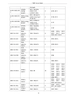
2RS1-16-184J
R flake
resistor
1608, 180K±5%
1
R3041
2RS1-16-364J
flake resistor
1608, 360K±5%
1
R3049
2RS1-16-562J
R flake
resistor
1608, 5.6K±5%
2
R3050, R6000
2RS1-16-153J
R flake
resistor
1608, 15K±5%
2
R3051, R6005
2RS1-16-560J
R flake
resistor
1608,
56Ω±5%
2
R3052, L4000
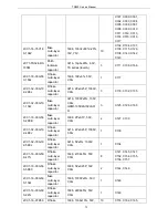
2RS1-16-511J
flake resistor
1608,
510Ω±5%
1
R4000
2RS1-16-203J
R flake
resistor
1608, 20K±5%
1
R4001
2RS1-16-513J
R flake
resistor
1608, 51K±5%
1
R6001
2RS1-16-273J
R flake
resistor
1608, 27K±5%
2
R6008, R6010
2RS1-16-362J
R flake
resistor
1608, 3.6K±5%
1
R6011
1TC1-UMC4
R patch
compound
tube
UMC4, NPN/PNP
compound tube
2
U1000, U3000
1IS1-AD9864
IF digital
system
AD9864,
LFCSP-N48_B7X6_75_P
0_5, pb-free
1
U4000
1IS1-LM2941S
Patch
specialized IC
LM2941S/TO-236, 5PIN,
pb-free
1
U5000
5FQ1-LFCN-400
Low pass filter
LFCN-400, 8.5W, DC to
400MHz, FV1206,
Mini-Circuits
1
U5002
5OT1-12R8-CEC
3-0503
R patch
temperature
compensated
crystal
oscillator
NT5032SA/NT5032SC,
12.8MHz±2.5PPm,
5.0*3.2*1.6mm
1
X1000
5FC1-DSF51R6
M-0705
R patch
crystal filter,
PT568/78/72/
DSF753SBF,
51.65MHz±4KHz/3dB,
7.0*5.0*1.3,
2
Z3000, Z3001
64
Summary of Contents for TR850
Page 1: ......
Page 45: ...TR850 Service Manual 5 4 Connection 1 2 3 4 6 8 7 5 9 10 13 14 15 16 18 17 11 12 41 ...
Page 90: ...TR850 Service Manual Figure 1 Rx Module Top Board PCB View 86 ...
Page 91: ...TR850 Service Manual Figure 2 Rx Module Bottom Board PCB View 87 ...
Page 93: ...TR850 Service Manual Figure 5 Power Amplifier Module Bottom Board PCB View 89 ...
Page 94: ...TR850 Service Manual Figure 6 Baseband Mainboard Top Board PCB View 90 ...
Page 95: ...TR850 Service Manual Figure 7 Baseband Mainboard Bottom Board PCB View 91 ...
Page 97: ...TR850 Service Manual Figure 10 Power Board Top Board PCB View 93 ...
Page 114: ...TR850 Service Manual Figure 16 Baseband Mainbaord Schematic Diagram 110 ...
Page 169: ...TR850 Service Manual Figure 1 Rx module Top Board Position Mark Diagram 165 ...
Page 170: ...TR850 Service Manual Figure 2 Rx Module Buttom Board Position Mark Diagram 166 ...
Page 172: ...TR850 Service Manual Figure 5 Power Amplifier Module Buttom Position Mark Diagram 168 ...
Page 173: ...TR850 Service Manual Figure 6 Baseband Mainboard Top Board Position Mark Diagram 169 ...
Page 174: ...TR850 Service Manual Figure 7 Baseband Mainboard Buttom Board Position Mark Diagram 170 ...
Page 176: ...TR850 Service Manual Figure 10 Power Board Top Board Position Mark Diagram 172 ...
Page 193: ...TR850 Service Manual Figure 16 Baseband Mainboard Schematic Diagram 189 ...


