


TR850 Service Manual
capacitor
2RS1-16-301J
Flake resistor
1
R144
3SE1-SDIP-04
SMD DIPdial switch
1
J4
6PM7-4071-HBC
Sepura repeater
baseband board PCB
1
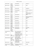
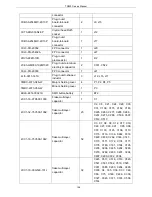
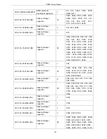
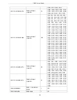
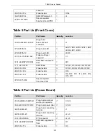
Table 5 Part List(Front Cover)
Part No.
Part Name
Quantity
Location
3CB3-A2548WV-2X05P
Plug-in unit
board-to-board
connector
1
J1
4PE3-0705-F4
Plug-in unit LED
8
LED1, LED2, LED3, LED4, LED5,
LED6, LED7, LED9
4PE3-0705-F2
Plug-in unit LED
1
LED8
2CC1-16-Y5V500-104Z
Flake multi-layer
capacitor
1
C1
5FE1-BLM18PG181SN1
SMD EMI suppression
filter
1
FB1
1TT1-DTC114YE
SMD triode
8
Q1, Q2, Q3, Q4, Q5, Q6, Q7, Q8
2RS1-16-330J
Flake resistor
8
R1, R2, R3, R4, R5, R6, R7, R8
2RS1-16-102J
Flake resistor
1
R16
2RS1-16-101J
Flake resistor
8
R9, R10, R11, R12, R13, R14,
R15, R17
6PD7-4071-HFB
Sepura repeater
frontcover PCB
1
Table 6 Part List(Power Board)
Part No.
Part Name
Quantity
Location
2CE3-GM350-102M1320
Plug-in unit aluminum
electrolytic capacitor
2
C1, C2
3SJ3-G8P-1C4P-12VDC
Plug-in unit power relay 2
U1, U2
3WPC-KF65-4P
Plug-in unit connecting
terminal
1
J1
3WPC-KF65-2P
Plug-in unit connecting
terminal
2
J2, J3
3CL3-PH-25402A
FPC connector
2
J4, J5
5FE1-BLM18PG181SN1
SMD EMI suppression
filter
1
R1
2RS1-16-471J
Flake resistor
1
R3
163
Summary of Contents for TR850
Page 1: ......
Page 45: ...TR850 Service Manual 5 4 Connection 1 2 3 4 6 8 7 5 9 10 13 14 15 16 18 17 11 12 41 ...
Page 90: ...TR850 Service Manual Figure 1 Rx Module Top Board PCB View 86 ...
Page 91: ...TR850 Service Manual Figure 2 Rx Module Bottom Board PCB View 87 ...
Page 93: ...TR850 Service Manual Figure 5 Power Amplifier Module Bottom Board PCB View 89 ...
Page 94: ...TR850 Service Manual Figure 6 Baseband Mainboard Top Board PCB View 90 ...
Page 95: ...TR850 Service Manual Figure 7 Baseband Mainboard Bottom Board PCB View 91 ...
Page 97: ...TR850 Service Manual Figure 10 Power Board Top Board PCB View 93 ...
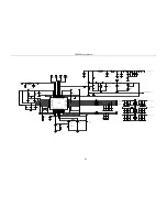
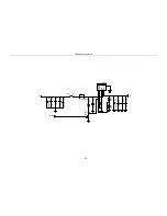
Page 114: ...TR850 Service Manual Figure 16 Baseband Mainbaord Schematic Diagram 110 ...
Page 169: ...TR850 Service Manual Figure 1 Rx module Top Board Position Mark Diagram 165 ...
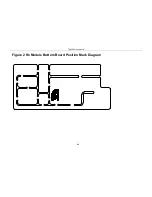
Page 170: ...TR850 Service Manual Figure 2 Rx Module Buttom Board Position Mark Diagram 166 ...
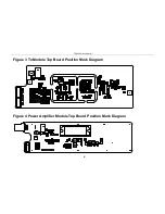
Page 172: ...TR850 Service Manual Figure 5 Power Amplifier Module Buttom Position Mark Diagram 168 ...
Page 173: ...TR850 Service Manual Figure 6 Baseband Mainboard Top Board Position Mark Diagram 169 ...
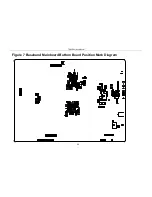
Page 174: ...TR850 Service Manual Figure 7 Baseband Mainboard Buttom Board Position Mark Diagram 170 ...
Page 176: ...TR850 Service Manual Figure 10 Power Board Top Board Position Mark Diagram 172 ...
Page 193: ...TR850 Service Manual Figure 16 Baseband Mainboard Schematic Diagram 189 ...


