


TR850 Service Manual
119
R166
49.9 1%
R169
4.7K
C178
0.1uF
R172
4.87K 1%
C172
0.1uF
C174
0.1uF
C180
0.1uF
R190
10K
2
TD-
3
RD+
4
CT_T
5
CT_R
6
RD-
7
NC
8
CH_GND
13
CH_GND
14
CH_GND
9
G
10
10
11
11
12
Y
1
TD+
15
16
J12
J00_0061NL
FB16
0
R187
10K
D12
MA2S111
R162
nc
10K
R176
10K
C171
0.1uF
R164
33R
OE
OUT
VSS
VDD
4
1
3
2
Y3
50MHz
R168
49.9 1%
C177
0.1uF
R173
7.5M
R191
NC
R175
10K
R161
4.7K
R160
49.9 1%
C297
0.1uF
R189
10K
C179
+
10uF/16V
1
TX_CLK
2
TX_EN
3
TXD0
4
TXD1
5
TXD2
6
TXD3/SMI_MODE
43
RXD0/PHYAD1
44
RXD1/PHYAD2
45
RXD2/PHYAD3
46
RXD3/PHYAD4
41
RX_ER/MDIX_EN
39
RX_DV/MII_MODE
38
RX_CLK
42
COL/PHYAD0
40
CRS/CRS_DV/LED_CFG
31
MDC
30
MDIO
29
RESET_N
7
PWR_DOWN/INT
33
X2
34
X1
25
25MHZ_OUT
24
RBIAS
37
PFBIN2
18
PFBIN1
23
PFBOUT
TD+
17
TD-
16
RD+
14
RD-
13
NC1
8
NC2
9
NC3
10
NC4
11
NC5
12
LED_LINK/AN0
28
LED_SPEED/AN1
27
LED_ACT/COL/AN_EN
26
NC7
21
NC6
20
AVDD33
22
IOVDD33
48
IOVDD33
32
AGND
15
AGND
19
IOGND
35
IOGND
47
DGND
36
U17
DP83848C
C181
0.1uF
FB15
BLM18PG181SN1
R188
10K
+
C175
10uF/25V
R178
NC
+
C176
10uF/16V
R163
10K
C173
1000PF/1KV
R192
10K
R174
10K
FB14
BLM18PG181SN1
R167
49.9 1%
R177
10K
D11
MA2S111
L32
22nH
L33
18nH
C244
0.1uF
C245
100P
C320
10n
C241
10n
C310
7P
C311
9P
C312
15P
C313
39P
C314
24P
C374
100P
C375
33P
C376
470P
C377
33P
C378
470P
C517
100P
C518
100P
C519
100P
C520
100P
R142
100R
R143
100R
50M
3V3_PYH
3V3_PYH
3V3A_PYH
3V3_PYH
3V3_PYH
3V3_PYH
3V3_PYH
3V3_PYH
3V3_PYH
3V3_PYH
3V3_LDO
3V3_PYH
3V3_PYH
3V3_PYH
3V3_PYH
3V3A_PYH
3V3A_PYH
3V3_PYH
PHY_RESET#
PHY_INT
RMII_TXD0
RMII_TXD1
RMII_TXEN
RMII_RXD0
RMII_RXD1
RMII_CRSDV
RMII_RX_ER
MDIO_D
MDIO_CLK
RMII_REF_CLK
50MHZ
RMII_RESET#
RMII_RESET#
50MHZ
TD+
TD-
RD+
RD-
PHY_LED0
PHY_LED1
TD+
TD-
RD+
RD-
PHY_LED1
PHY_LED0
Summary of Contents for TR850
Page 1: ......
Page 45: ...TR850 Service Manual 5 4 Connection 1 2 3 4 6 8 7 5 9 10 13 14 15 16 18 17 11 12 41 ...
Page 90: ...TR850 Service Manual Figure 1 Rx Module Top Board PCB View 86 ...
Page 91: ...TR850 Service Manual Figure 2 Rx Module Bottom Board PCB View 87 ...
Page 93: ...TR850 Service Manual Figure 5 Power Amplifier Module Bottom Board PCB View 89 ...
Page 94: ...TR850 Service Manual Figure 6 Baseband Mainboard Top Board PCB View 90 ...
Page 95: ...TR850 Service Manual Figure 7 Baseband Mainboard Bottom Board PCB View 91 ...
Page 97: ...TR850 Service Manual Figure 10 Power Board Top Board PCB View 93 ...
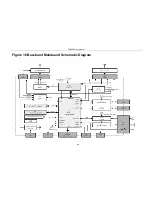
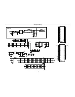
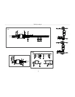
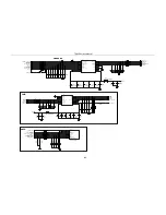
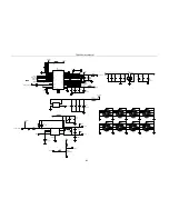
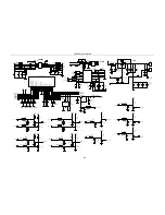
Page 114: ...TR850 Service Manual Figure 16 Baseband Mainbaord Schematic Diagram 110 ...
Page 169: ...TR850 Service Manual Figure 1 Rx module Top Board Position Mark Diagram 165 ...
Page 170: ...TR850 Service Manual Figure 2 Rx Module Buttom Board Position Mark Diagram 166 ...
Page 172: ...TR850 Service Manual Figure 5 Power Amplifier Module Buttom Position Mark Diagram 168 ...
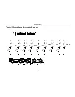
Page 173: ...TR850 Service Manual Figure 6 Baseband Mainboard Top Board Position Mark Diagram 169 ...
Page 174: ...TR850 Service Manual Figure 7 Baseband Mainboard Buttom Board Position Mark Diagram 170 ...
Page 176: ...TR850 Service Manual Figure 10 Power Board Top Board Position Mark Diagram 172 ...
Page 193: ...TR850 Service Manual Figure 16 Baseband Mainboard Schematic Diagram 189 ...