


TR850 Service Manual
send into the internal DSP. In the meantime, converts the received digital audio from the internal DSP to
analog audio, then send the audio to audio power amplifier(U31), before finally send to the ACCY external
interface, which i
s to drive the 1W, 16Ω speaker.
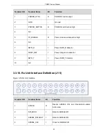
3.3.4. Ethernet Interface
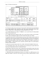
Figure 3-12 Ethernet Interface
As Figure 3-12 shows, A RMII simplified interface is used between the CUP(U4) and network interface
chip(U17) .
RMII interface independent clock uses external clock mode and share 50MHz clock with U17.
CPU (U4) achieves the hardware information of internet interface U17 through the independent
configuration interface MDIO. CPU also initiate it and assign MAC and IP address.
The data transmitting and receiving between network interface chip(U17) and interface connector(J12) are
achieved through connecting the transformer inside the connector jack RJ45 and LED through 2 pairs of
differential line.
The network interface can realize parameter adjustment
and parameter configure, user programming and
firmware upgrade.
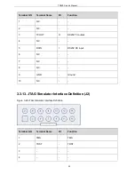
3.3.5. Boot Mode
A boot mode selection switch (J4) is provided on the baseband. The four position 1 to 4 of DIP encode
switcher are correspondingly connected with boot 1 to boot 4 of OMAP (U4), so the boot operation mode
will be changed after being powered on.
The level of position “ON” of encode switcher corresponding to boot which is connected to GND is
“
0”.Conversely, the level of position “OFF” is “1”.
As showing in Figure 3-13, the level of boot1 to boot4 of switcher is 0101, and it enters to firmware
download mode after power on. It can upgrade the guide program and the low driver program by booting
from serial port(UART2).
15
Summary of Contents for TR850
Page 1: ......
Page 45: ...TR850 Service Manual 5 4 Connection 1 2 3 4 6 8 7 5 9 10 13 14 15 16 18 17 11 12 41 ...
Page 90: ...TR850 Service Manual Figure 1 Rx Module Top Board PCB View 86 ...
Page 91: ...TR850 Service Manual Figure 2 Rx Module Bottom Board PCB View 87 ...
Page 93: ...TR850 Service Manual Figure 5 Power Amplifier Module Bottom Board PCB View 89 ...
Page 94: ...TR850 Service Manual Figure 6 Baseband Mainboard Top Board PCB View 90 ...
Page 95: ...TR850 Service Manual Figure 7 Baseband Mainboard Bottom Board PCB View 91 ...
Page 97: ...TR850 Service Manual Figure 10 Power Board Top Board PCB View 93 ...
Page 114: ...TR850 Service Manual Figure 16 Baseband Mainbaord Schematic Diagram 110 ...
Page 169: ...TR850 Service Manual Figure 1 Rx module Top Board Position Mark Diagram 165 ...
Page 170: ...TR850 Service Manual Figure 2 Rx Module Buttom Board Position Mark Diagram 166 ...
Page 172: ...TR850 Service Manual Figure 5 Power Amplifier Module Buttom Position Mark Diagram 168 ...
Page 173: ...TR850 Service Manual Figure 6 Baseband Mainboard Top Board Position Mark Diagram 169 ...
Page 174: ...TR850 Service Manual Figure 7 Baseband Mainboard Buttom Board Position Mark Diagram 170 ...
Page 176: ...TR850 Service Manual Figure 10 Power Board Top Board Position Mark Diagram 172 ...
Page 193: ...TR850 Service Manual Figure 16 Baseband Mainboard Schematic Diagram 189 ...


