


TR850 Service Manual
Audio Generator
Measurement Range: 50Hz~5KHz or higher
Output: 0~1V
Spectrum Tester
Capacity: 3% or lower at 1KHz
Input Level: 50mV~10Vms
Spectrum Analyzer
Measurement Rnage: 100~3GHz or higher
5
Ω
dummy load
100W
Voltage Stabilization Power
Supply
Output Voltage: 5V~30V; Current: 20A
Integrated Tester
HP8921, IFR3920
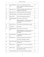
9. Troubleshooting
No.
Problems
Causes and Solution
1
Short coverage
1. Check the duplexer isolation, and whether the insertion loss
meets the requirement.
2. Check if there is any feeder connecting damage or abnormality.
3. Check if the antenna frequency range matches with the
repeater, and check if the antenna is broken.
4. Check if there is high power radio antenna beside the repeater
2
Unable to repeat
1. Check if the settings such as terminal frequency, CTCSS,
CDCSS, color code, repeater slot are correct.
2. Check if there is interference on the uplink frequency.
3. Beyond the communication scope.
3
Unable to receive
1. Bad antenna contact. Please fix the antenna tightly.
2. Inconsistent frequency between Tx and Rx. Please select the
same frequency.
3. Beyond the communication scope.
4
Rx green light is on
without being able to
repeat
Check if the settings such as terminal frequency, CTCSS, CDCSS,
color code, repeater slot are correct.
52
Summary of Contents for TR850
Page 1: ......
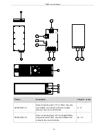
Page 45: ...TR850 Service Manual 5 4 Connection 1 2 3 4 6 8 7 5 9 10 13 14 15 16 18 17 11 12 41 ...
Page 90: ...TR850 Service Manual Figure 1 Rx Module Top Board PCB View 86 ...
Page 91: ...TR850 Service Manual Figure 2 Rx Module Bottom Board PCB View 87 ...
Page 93: ...TR850 Service Manual Figure 5 Power Amplifier Module Bottom Board PCB View 89 ...
Page 94: ...TR850 Service Manual Figure 6 Baseband Mainboard Top Board PCB View 90 ...
Page 95: ...TR850 Service Manual Figure 7 Baseband Mainboard Bottom Board PCB View 91 ...
Page 97: ...TR850 Service Manual Figure 10 Power Board Top Board PCB View 93 ...
Page 114: ...TR850 Service Manual Figure 16 Baseband Mainbaord Schematic Diagram 110 ...
Page 169: ...TR850 Service Manual Figure 1 Rx module Top Board Position Mark Diagram 165 ...
Page 170: ...TR850 Service Manual Figure 2 Rx Module Buttom Board Position Mark Diagram 166 ...
Page 172: ...TR850 Service Manual Figure 5 Power Amplifier Module Buttom Position Mark Diagram 168 ...
Page 173: ...TR850 Service Manual Figure 6 Baseband Mainboard Top Board Position Mark Diagram 169 ...
Page 174: ...TR850 Service Manual Figure 7 Baseband Mainboard Buttom Board Position Mark Diagram 170 ...
Page 176: ...TR850 Service Manual Figure 10 Power Board Top Board Position Mark Diagram 172 ...
Page 193: ...TR850 Service Manual Figure 16 Baseband Mainboard Schematic Diagram 189 ...


