


TR850 Service Manual
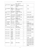
12nH±2%
2LW1-20UC-180
J
R Patch
winding
inductor
2012, 18nH±5%,
ceramic core
(C2012C-18NJ)
2
L209, L210
2LW1-20UC-331
J
Patch winding
inductor
2012, 330nH±5%,
ceramic core (high
frequency)
2
L106, L118
2LW1-20UC-8R2
J
Patch winding
inductor
2012, 8.2nH±5%,
ceramic core
(C2012C-8N2J)
1
L107
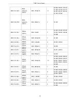
2LW1-25UC-103
J
R Patch
winding
inductor
2520,
10μH±5%,
ceramic core
(FLM2520-100J)
1
L122
2RE1-16-1000
Patch
precision
resistor
1608,
100Ω±1%
9
R105,
R106,
R113,
R115,
R117,
R119,
R120, R121, R128
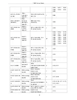
2RE1-16-1001
Patch
precision
resistor
1608, 1K±1%
2
R134, R135
2RE1-16-1200
Patch
precision
resistor
1608,
120Ω±1%
2
R108, R129
2RE1-16-1801
Patch
precision
resistor
1608, 1.8K±1%
1
C339
2RE1-16-47R0
Patch
precision
resistor
1608,
47Ω±1%
1
R124
2RE1-16-8201
R Patch
precision
resistor
1608, 8.2K±1%
2
R342, R403
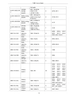
2RS1-16-000O
R Flake
resistor
1608,
0Ω
23
R122,
R123,
R125,
R130,
R131,
R137,
R138,
C191,
R210,
L211,
R313,
R314,
R315,
R316,
R319,
R320,
R325,
R326,
R334,
R335,
R346,
R348, R350
2RS1-16-103J
R Flake
resistor
1608, 10K±5%
9
R114,
R132,
R133,
R140,
R141,
R142,
R143, R144, R145
2RS1-16-104J
R Flake
resistor
1608, 100K±5%
6
R100,
R103,
R107,
R111, R118, R127
2RS1-16-123J
R Flake
resistor
1608, 12K±5%
2
R337, R343
70
Summary of Contents for TR850
Page 1: ......
Page 45: ...TR850 Service Manual 5 4 Connection 1 2 3 4 6 8 7 5 9 10 13 14 15 16 18 17 11 12 41 ...
Page 90: ...TR850 Service Manual Figure 1 Rx Module Top Board PCB View 86 ...
Page 91: ...TR850 Service Manual Figure 2 Rx Module Bottom Board PCB View 87 ...
Page 93: ...TR850 Service Manual Figure 5 Power Amplifier Module Bottom Board PCB View 89 ...
Page 94: ...TR850 Service Manual Figure 6 Baseband Mainboard Top Board PCB View 90 ...
Page 95: ...TR850 Service Manual Figure 7 Baseband Mainboard Bottom Board PCB View 91 ...
Page 97: ...TR850 Service Manual Figure 10 Power Board Top Board PCB View 93 ...
Page 114: ...TR850 Service Manual Figure 16 Baseband Mainbaord Schematic Diagram 110 ...
Page 169: ...TR850 Service Manual Figure 1 Rx module Top Board Position Mark Diagram 165 ...
Page 170: ...TR850 Service Manual Figure 2 Rx Module Buttom Board Position Mark Diagram 166 ...
Page 172: ...TR850 Service Manual Figure 5 Power Amplifier Module Buttom Position Mark Diagram 168 ...
Page 173: ...TR850 Service Manual Figure 6 Baseband Mainboard Top Board Position Mark Diagram 169 ...
Page 174: ...TR850 Service Manual Figure 7 Baseband Mainboard Buttom Board Position Mark Diagram 170 ...
Page 176: ...TR850 Service Manual Figure 10 Power Board Top Board Position Mark Diagram 172 ...
Page 193: ...TR850 Service Manual Figure 16 Baseband Mainboard Schematic Diagram 189 ...


