
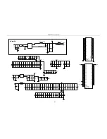


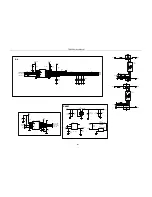
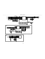
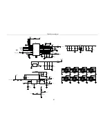


TR850 Service Manual
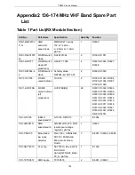
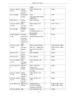
Appendix2 136-174 MHz VHF Band Spare Part
List
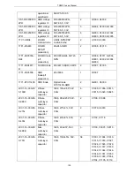
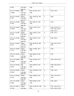
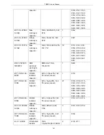
Table 1 Part List(RX Module Section)
Part No.
Part Name
Specification
Quantity
Position
1DR1-MM3Z15V
T1G
SMD
anti-static
zener diode
MM3Z2V4T1 series,
15V, W=1.2mm,
L=2.5mm, H=1.0mm,
pb-free
1
D5000
1DS1-DA2S1010
0L
R SMD switch
diode
DA2S10100L
2
D1000, D1001
1DS1-HSC277
R SMD switch
diode (off
production)
HSC277, 1608
4
D3025, D3026, D3027,
D3028
1DS1-RB706F-4
0
R SMD switch
diode
Schottky diode
RB706F-40, SOT-323
2
D3029, D3000
1DV1-1SV305
R SMD
varactor diode
1SV305
8
D1002, D1003, D1004,
D1005, D1006, D1007,
D1008, D1009
1DV1-HVC376B
R SMD
varactor diode
(off
production)
HVC376B(B9)
26
D3001, D3002, D3003,
D3004, D3005, D3006,
D3007, D3008, D3009,
D3010, D3011, D3012,
D3013, D3014, D3015,
D3016, D3017, D3018,
D3019, D3020, D3021,
D3022, D3023, D3024,
D4000, D4001
1IS1-GT3136
E SMD
specialized IC
GT3136, SSOP16
1
IC3004
1IS1-LM2941S
SMD
specialized IC
LM2941S/TO-236, 5PIN,
low dropout voltage
regulator, pb-free
1
U5000
1IS1-PGA103
Broad band
low noise
amplifier
PGA-103+, 0.05to4GHz,
SOT-89, PACKAGE,
Mini-Circuits brand,
RoHS
3
IC6003, IC6004, IC6006
1IS1-SKY72310
PLL chip
SKY72310, 24 pin QFN
4mmX4mm
pb-free(QFN-N24_B4x4-
P0_5), pb-free
1
IC1000
1IS1-TC75S51F
SMD single
TC75S51F,
2
IC6001, IC6002
128
Summary of Contents for TR850
Page 1: ......
Page 45: ...TR850 Service Manual 5 4 Connection 1 2 3 4 6 8 7 5 9 10 13 14 15 16 18 17 11 12 41 ...
Page 90: ...TR850 Service Manual Figure 1 Rx Module Top Board PCB View 86 ...
Page 91: ...TR850 Service Manual Figure 2 Rx Module Bottom Board PCB View 87 ...
Page 93: ...TR850 Service Manual Figure 5 Power Amplifier Module Bottom Board PCB View 89 ...
Page 94: ...TR850 Service Manual Figure 6 Baseband Mainboard Top Board PCB View 90 ...
Page 95: ...TR850 Service Manual Figure 7 Baseband Mainboard Bottom Board PCB View 91 ...
Page 97: ...TR850 Service Manual Figure 10 Power Board Top Board PCB View 93 ...
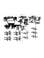
Page 114: ...TR850 Service Manual Figure 16 Baseband Mainbaord Schematic Diagram 110 ...
Page 169: ...TR850 Service Manual Figure 1 Rx module Top Board Position Mark Diagram 165 ...
Page 170: ...TR850 Service Manual Figure 2 Rx Module Buttom Board Position Mark Diagram 166 ...
Page 172: ...TR850 Service Manual Figure 5 Power Amplifier Module Buttom Position Mark Diagram 168 ...
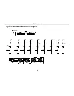
Page 173: ...TR850 Service Manual Figure 6 Baseband Mainboard Top Board Position Mark Diagram 169 ...
Page 174: ...TR850 Service Manual Figure 7 Baseband Mainboard Buttom Board Position Mark Diagram 170 ...
Page 176: ...TR850 Service Manual Figure 10 Power Board Top Board Position Mark Diagram 172 ...
Page 193: ...TR850 Service Manual Figure 16 Baseband Mainboard Schematic Diagram 189 ...