


TR850 Service Manual
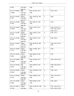
capacitor
2CC1-32-C0G50
0-120J
flake
multi-layer
capacitor
3216,12P±5%,50V,C0G
2
C132,C135
2CC1-32-C0G50
0-270J
flake
multi-layer
capacitor
3216,27P±5%,50V,C0G
2
C133,C134
2CC1-16-C0G50
0-330J
flake
multi-layer
capacitor
1608,33P±5%,50V,C0G
4
C144,C146,C168,C169
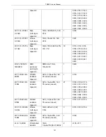
2CC1-32-C0G10
1-102J
flake
multi-layer
capacitor
3216,1000P±5%,100V,C
0G,GRM3195C2A102JA
01D
3
C125,C126,C160
2CC1-16-C0G50
0-220J
R flake
multi-layer
capacitor
1608,22P±5%,50V,C0G
4
C127,C128,C130,C131
2CC1-16-C0G50
0-471J
R flake
multi-layer
capacitor
1608,470P±5%,50V,C0
G
8
C141,C145,C147,C152,
C154,C155,C156,C157
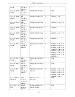
2CC1-16-C0G50
0-102J
flake
multi-layer
capacitor
1608,1000P±5%,50V,C0
G
1
C148
2CC1-16-C0G50
0-221J
R flake
multi-layer
capacitor
1608,220P±5%,50V,C0
G
1
C149
2CC1-16-X7R50
0-103K
R flake
multi-layer
capacitor
1608,10nF±10%,50V,X7
R
10
C153,C162,C165,C200,
C201,C202,C204,C206,
C207,C208
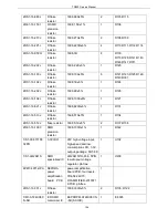
2CT1-TS32-100-
220M
SMD tantalum
capacitor
3216,22μF±20%,10V,TS
series (A level)
1
C205
1DR1-MM3Z15V
T1G
SMD
anti-static
zener diode
MM3Z2V4T1 TS series,
15V,W=1.2mm,L=2.5mm
,H=1.0mm, pb-free
3
D100,D101,D200
1DZ1-HZU5ALL
R SMD
voltage
regulator
diode (off
production)
HZU5ALL,2012,5V
1
D102
1DS1-RB706F-4
0
R SMD switch
diode
Schottky diode
RB706F-40,SOT-323
2
D103,D104
1DR1-XBS053V
15R-1G
SMD schottky
diode
XBS053V15R-1G,
SOD-523 package,
VR=20V,VF=0.40V,
pb-free
2
D201,D202
1IL1-NJM2904V
R SMD linear
IC
Double operational
amplification
1
IC100
152
Summary of Contents for TR850
Page 1: ......
Page 45: ...TR850 Service Manual 5 4 Connection 1 2 3 4 6 8 7 5 9 10 13 14 15 16 18 17 11 12 41 ...
Page 90: ...TR850 Service Manual Figure 1 Rx Module Top Board PCB View 86 ...
Page 91: ...TR850 Service Manual Figure 2 Rx Module Bottom Board PCB View 87 ...
Page 93: ...TR850 Service Manual Figure 5 Power Amplifier Module Bottom Board PCB View 89 ...
Page 94: ...TR850 Service Manual Figure 6 Baseband Mainboard Top Board PCB View 90 ...
Page 95: ...TR850 Service Manual Figure 7 Baseband Mainboard Bottom Board PCB View 91 ...
Page 97: ...TR850 Service Manual Figure 10 Power Board Top Board PCB View 93 ...
Page 114: ...TR850 Service Manual Figure 16 Baseband Mainbaord Schematic Diagram 110 ...
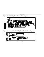
Page 169: ...TR850 Service Manual Figure 1 Rx module Top Board Position Mark Diagram 165 ...
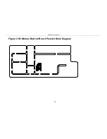
Page 170: ...TR850 Service Manual Figure 2 Rx Module Buttom Board Position Mark Diagram 166 ...
Page 172: ...TR850 Service Manual Figure 5 Power Amplifier Module Buttom Position Mark Diagram 168 ...
Page 173: ...TR850 Service Manual Figure 6 Baseband Mainboard Top Board Position Mark Diagram 169 ...
Page 174: ...TR850 Service Manual Figure 7 Baseband Mainboard Buttom Board Position Mark Diagram 170 ...
Page 176: ...TR850 Service Manual Figure 10 Power Board Top Board Position Mark Diagram 172 ...
Page 193: ...TR850 Service Manual Figure 16 Baseband Mainboard Schematic Diagram 189 ...


