

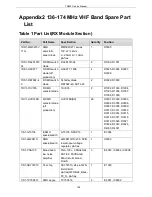


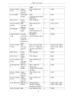


TR850 Service Manual
0-681J
multi-layer
capacitor
C0G
2CC1-16-X7R16
0-104K
flake
multi-layer
capacitor
1608, 100nF±10%, 16V,
X7R
2
C4015, C4058
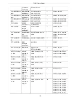
0SS2-4095-HRA
STR-V RX
board plug-in
unit
STR-V RX board plug-in
unit, pb-free
1
D1000
3CB3-A2548WV-
2X13P
Plug-in
board-to-boar
d connector
2*13 socket(male), 180
degrees,
interval2.54mm,
40.64X9X9.1mm
1
J6000
3CR7-SMA-50K
WE-2
RF coaxial
connector
SMA-50KWE-2, 5PIN
plug-in unit, 90 degrees,
length
23mm.pitch:2.54mm
2
J3000, J3002
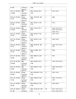
6SS2-4095-HTA
STR-V TX
board suite
(131031)
Sepura VHF repeater,
STR-V TX board suite,
pb-free
1
6SS1-4095-HTA
STR-V TX
board SMD
material(1310
31)
Sepura VHF repeater,
STR-V TX board SMD
material, pb-free
1
D105, D110
3FW1-42932-30
2320
R SMD fuse
429003/433003/466003,
3216, 3A/32V
1
CB400
1DR1-MM3Z12V
T1G
Anti-static
zener diode
MM3Z12VT1G, 3V,
SOD323, pb-free
1
D400
1DS1-HSC277
R SMD switch
diode(off
production)
HSC277, 1608
1
D100
1DV1-1SV278
R SMD
varactor diode
1SV278(T1)
2
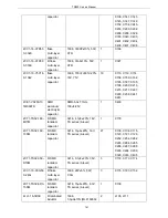
D105, D110
1DV1-1SV305
R SMD
varactor diode
1SV305
8
D101, D102, D103,
D104, D106, D107,
D108, D109
1IS1-LM2941S
SMD
specialized IC
LM2941S/TO-236, 5PIN,
low dropout voltage
regulator,pb-free
1
U400
1IS1-SKY72310
PLL chip
SKY72310, 24 pin QFN
4mmX4mm
pb-free(QFN-N24_B4x4-
P0_5), pb-free
1
IC100
1IS1-PGA103
Broad band
low niose
amplifier
PGA-103+, 0.05to4GHz,
SOT-89, PACKAGE,
Mini-Circuits brand,
RoHS
1
IC306
138
Summary of Contents for TR850
Page 1: ......
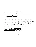
Page 45: ...TR850 Service Manual 5 4 Connection 1 2 3 4 6 8 7 5 9 10 13 14 15 16 18 17 11 12 41 ...
Page 90: ...TR850 Service Manual Figure 1 Rx Module Top Board PCB View 86 ...
Page 91: ...TR850 Service Manual Figure 2 Rx Module Bottom Board PCB View 87 ...
Page 93: ...TR850 Service Manual Figure 5 Power Amplifier Module Bottom Board PCB View 89 ...
Page 94: ...TR850 Service Manual Figure 6 Baseband Mainboard Top Board PCB View 90 ...
Page 95: ...TR850 Service Manual Figure 7 Baseband Mainboard Bottom Board PCB View 91 ...
Page 97: ...TR850 Service Manual Figure 10 Power Board Top Board PCB View 93 ...
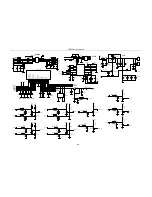
Page 114: ...TR850 Service Manual Figure 16 Baseband Mainbaord Schematic Diagram 110 ...
Page 169: ...TR850 Service Manual Figure 1 Rx module Top Board Position Mark Diagram 165 ...
Page 170: ...TR850 Service Manual Figure 2 Rx Module Buttom Board Position Mark Diagram 166 ...
Page 172: ...TR850 Service Manual Figure 5 Power Amplifier Module Buttom Position Mark Diagram 168 ...
Page 173: ...TR850 Service Manual Figure 6 Baseband Mainboard Top Board Position Mark Diagram 169 ...
Page 174: ...TR850 Service Manual Figure 7 Baseband Mainboard Buttom Board Position Mark Diagram 170 ...
Page 176: ...TR850 Service Manual Figure 10 Power Board Top Board Position Mark Diagram 172 ...
Page 193: ...TR850 Service Manual Figure 16 Baseband Mainboard Schematic Diagram 189 ...


