


TR850 Service Manual
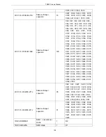
R130, R210, L211,
R325, R326, R334,
R346, R348, R319,
R320, R350, R313,
R314, R315, R316
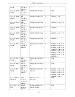
2RS1-16-103J
R flake
resistor
1608, 10K±5%
9
R114, R132, R133,
R140, R141, R142,
R143, R144, R145
2RS1-16-104J
R flake
resistor
1608, 100K±5%
6
R100, R103, R107,
R111, R118, R127
2RS1-16-123J
R flake
resistor
1608, 12K±5%
2
R343, R337
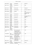
2RS1-16-124J
R flake
resistor
1608, 120K±5%
2
R339, R341
2RS1-16-220J
R flake
resistor
1608,
22Ω±5%
1
R218
2RS1-16-221J
R flake
resistor
1608,
220Ω±5%
2
R211, R212
2RS1-16-270J
R flake
resistor
1608,
27Ω±5%
2
R209, R125
2RS1-16-302J
flake resistor
1608, 3K±5%
2
R104, R116
2RS1-16-472J
R flake
resistor
1608, 4.7K±5%
2
R101, R109
2RS1-16-473J
R flake
resistor
1608, 47K±5%
5
R345, R110, R220,
R400, R401
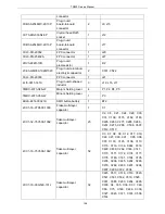
2RS1-16-511J
flake resistor
1608,
510Ω±5%
1
R219
2RS1-16-563J
R flake
resistor
1608, 56K±5%
1
R207
2RS1-16-682J
R flake
resistor
1608, 6.8K±5%
2
R102, R112
2RS1-20-000O
R flake
resistor
2012,
0Ω
2
L212, L213
5FE1-BLM11A60
1S
R SMD EMI
suppression
filter
1608,
BLM11A601S/BLM18AG
601S(0138-05)
28
L100, L101, L102, L108,
L109, L110, L112, L114,
L121, L123, L202, L207,
L300, R301, L301, R302,
R303, R304, R305,
R306, R307, R308,
R309, R310, R311,
R312, R329, R351
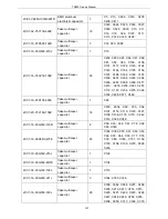
5FE1-BLM21P30
0S
R SMD EMI
suppression
filter
2012,
BLM21P300S/BLM21PG
300S(0149-05)
1
L400
5OT1-12R8-ACL
4-3225
SMD
temperature
compensated
KDS, 12.8MHz±1.5ppm,
Vc=1.5±1V, range:
±35ppm, -40
℃~
85,
1
X100
143
Summary of Contents for TR850
Page 1: ......
Page 45: ...TR850 Service Manual 5 4 Connection 1 2 3 4 6 8 7 5 9 10 13 14 15 16 18 17 11 12 41 ...
Page 90: ...TR850 Service Manual Figure 1 Rx Module Top Board PCB View 86 ...
Page 91: ...TR850 Service Manual Figure 2 Rx Module Bottom Board PCB View 87 ...
Page 93: ...TR850 Service Manual Figure 5 Power Amplifier Module Bottom Board PCB View 89 ...
Page 94: ...TR850 Service Manual Figure 6 Baseband Mainboard Top Board PCB View 90 ...
Page 95: ...TR850 Service Manual Figure 7 Baseband Mainboard Bottom Board PCB View 91 ...
Page 97: ...TR850 Service Manual Figure 10 Power Board Top Board PCB View 93 ...
Page 114: ...TR850 Service Manual Figure 16 Baseband Mainbaord Schematic Diagram 110 ...
Page 169: ...TR850 Service Manual Figure 1 Rx module Top Board Position Mark Diagram 165 ...
Page 170: ...TR850 Service Manual Figure 2 Rx Module Buttom Board Position Mark Diagram 166 ...
Page 172: ...TR850 Service Manual Figure 5 Power Amplifier Module Buttom Position Mark Diagram 168 ...
Page 173: ...TR850 Service Manual Figure 6 Baseband Mainboard Top Board Position Mark Diagram 169 ...
Page 174: ...TR850 Service Manual Figure 7 Baseband Mainboard Buttom Board Position Mark Diagram 170 ...
Page 176: ...TR850 Service Manual Figure 10 Power Board Top Board Position Mark Diagram 172 ...
Page 193: ...TR850 Service Manual Figure 16 Baseband Mainboard Schematic Diagram 189 ...


