


TR850 Service Manual
6
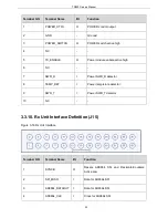
ACC_ID1
I
Reserved
7
O
Power 13.2VDC switched output
8
POWER_GND
-
Ground
9
EXT_SPK-
O
Annalog output speaker-
10
O
Analog output
11
TX_AUDIO
I
Analog audio input
12
AUDIO_GND
-
Ground
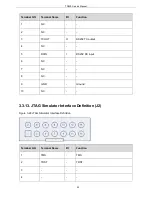
13
AUX_AUDIO_OUT1
O
Reserved
14
RX_AUDIO
I
Reserved
15
AUX_AUDIO_OUT2
O
Reserved
16
GND
-
Ground
17
PRGM_IO_1
I
PTT input,high active
18
GND
-
Ground
19
PRGM_IO_2
I/O
Reserved
20
PRGM_IO_6
I/O
Reserved
21
PRGM_IO_3
I/O
Reserved
22
PRGM_IO_7
O
Output high level(2.8V)
23
PRGM_IO_4
I/O
Reserved
24
PRGM_IO_8
I/O
Reserved
25
PRGM_IO_5
I/O
Reserved
26
PRGM_IO_9
I/O
Reserved
25
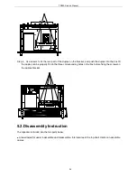
Summary of Contents for TR850
Page 1: ......
Page 45: ...TR850 Service Manual 5 4 Connection 1 2 3 4 6 8 7 5 9 10 13 14 15 16 18 17 11 12 41 ...
Page 90: ...TR850 Service Manual Figure 1 Rx Module Top Board PCB View 86 ...
Page 91: ...TR850 Service Manual Figure 2 Rx Module Bottom Board PCB View 87 ...
Page 93: ...TR850 Service Manual Figure 5 Power Amplifier Module Bottom Board PCB View 89 ...
Page 94: ...TR850 Service Manual Figure 6 Baseband Mainboard Top Board PCB View 90 ...
Page 95: ...TR850 Service Manual Figure 7 Baseband Mainboard Bottom Board PCB View 91 ...
Page 97: ...TR850 Service Manual Figure 10 Power Board Top Board PCB View 93 ...
Page 114: ...TR850 Service Manual Figure 16 Baseband Mainbaord Schematic Diagram 110 ...
Page 169: ...TR850 Service Manual Figure 1 Rx module Top Board Position Mark Diagram 165 ...
Page 170: ...TR850 Service Manual Figure 2 Rx Module Buttom Board Position Mark Diagram 166 ...
Page 172: ...TR850 Service Manual Figure 5 Power Amplifier Module Buttom Position Mark Diagram 168 ...
Page 173: ...TR850 Service Manual Figure 6 Baseband Mainboard Top Board Position Mark Diagram 169 ...
Page 174: ...TR850 Service Manual Figure 7 Baseband Mainboard Buttom Board Position Mark Diagram 170 ...
Page 176: ...TR850 Service Manual Figure 10 Power Board Top Board Position Mark Diagram 172 ...
Page 193: ...TR850 Service Manual Figure 16 Baseband Mainboard Schematic Diagram 189 ...


