


TR850 Service Manual
11
ACC_MAP_ID_1
Accessory ID input Line 1
Control signal, when
connected with Pin20, the
IP address will be set to
the default address:
192.168.1.100.
Digital Input:
(2.5V<VIH<5V,0V<VIL<0.4V)
12
Squelch
(Program_IO_6)
Digital Input. High level
will enable opening
squelch when connected
with Pin20.
Digital Input
(2.5V<VIH<5V,0V<VIL<0.4V)
13
RXD
Output.
Receive signal from
repeater to PC
RS232 Level:
-3V ~ -15V
+3V ~ +15V
14
TXD
Input.
Transmit signal from PC
to repeater
RS232 Level:
-3V ~ -15V
+3V ~ +15V
15
GND
Ground
-
16
Rx_Audio
NULL
-
17
Audio_Ground
Ground
-
18
Tx_Audio
External Audio signal
input
Analog input:0V<VIL<0.5V
19
GND
Ground
-
20
Program_IO_7
Output high level, used
with Pin7 (PTT function),
Pin10 (analog Rx
function) and Pin11 (IP
address reset function)
and pin23(open squelch)
Digital Output
2.5V<VOH<3.3V
21
Program_IO_4
(Emergency)
NULL
-
22
Program_IO_8
NULL
-
27
Summary of Contents for TR850
Page 1: ......
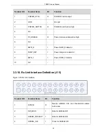
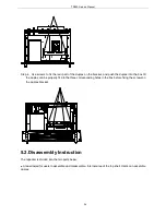
Page 45: ...TR850 Service Manual 5 4 Connection 1 2 3 4 6 8 7 5 9 10 13 14 15 16 18 17 11 12 41 ...
Page 90: ...TR850 Service Manual Figure 1 Rx Module Top Board PCB View 86 ...
Page 91: ...TR850 Service Manual Figure 2 Rx Module Bottom Board PCB View 87 ...
Page 93: ...TR850 Service Manual Figure 5 Power Amplifier Module Bottom Board PCB View 89 ...
Page 94: ...TR850 Service Manual Figure 6 Baseband Mainboard Top Board PCB View 90 ...
Page 95: ...TR850 Service Manual Figure 7 Baseband Mainboard Bottom Board PCB View 91 ...
Page 97: ...TR850 Service Manual Figure 10 Power Board Top Board PCB View 93 ...
Page 114: ...TR850 Service Manual Figure 16 Baseband Mainbaord Schematic Diagram 110 ...
Page 169: ...TR850 Service Manual Figure 1 Rx module Top Board Position Mark Diagram 165 ...
Page 170: ...TR850 Service Manual Figure 2 Rx Module Buttom Board Position Mark Diagram 166 ...
Page 172: ...TR850 Service Manual Figure 5 Power Amplifier Module Buttom Position Mark Diagram 168 ...
Page 173: ...TR850 Service Manual Figure 6 Baseband Mainboard Top Board Position Mark Diagram 169 ...
Page 174: ...TR850 Service Manual Figure 7 Baseband Mainboard Buttom Board Position Mark Diagram 170 ...
Page 176: ...TR850 Service Manual Figure 10 Power Board Top Board Position Mark Diagram 172 ...
Page 193: ...TR850 Service Manual Figure 16 Baseband Mainboard Schematic Diagram 189 ...


