


TR850 Service Manual
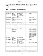
capacitor
C139, C141, C143,
C145, C147, C149,
C152, C154, C245,
C253, C290, C292,
C296, C298, C326,
C335, C343, C400,
C401, C402, C404,
C406, C407, C408
2CC1-16-X7R50
0-332K
flake
multi-layer
capacitor
1608, 3300P±10%, 50V,
X7R
1
C336
2CC1-16-X7R50
0-333K
R flake
multi-layer
capacitor
1608, 33nF±10%, 50V,
X7R
1
C327
2CC1-16-Y5V16
0-104Z
flake
multi-layer
capacitor
1608, 100nF+80%/-20%,
16V, Y5V
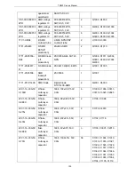
19
C110, C112, C114,
C158, C159, C162,
C185, C187, C195,
C196, C209, C213,
C215, C217, C227,
C229, C238, C241,
C243
2CE1-VS250-10
1M0607D
SMD
aluminum
electrolytic
capacitor
SMD-6.3x7.7mm,
100uF/25V
1
C403
2CT1-TS32-160-
4R7M
R SMD
tantalum
capacitor
3216,
4.7μF±20%, 16V,
TS series (A level)
1
C178
2CT1-TS32-160-
100M
R SMD
tantalum
capacitor
3216,
10μF±20%, 16V,
TS series (A level)
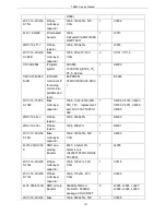
21
C100, C104, C115,
C120, C121, C126,
C252, C254, C282,
C283, C284, C285,
C286, C287, C288,
C293, C294, C299,
C328, C333, C405
2CT1-TS32-350-
R10M
R SMD
tantalum
capacitor
3216,
0.1μF±20%, 35V,
TS series (A level)
3
C172, C173, C174
2CC1-16-C0G50
0-240J
R flake
multi-layer
capacitor
1608, 24P±5%, 50V,
C0G
3
C176, C183, C132
2CT1-TS32-6R3-
150M
R SMD
tantalum
capacitor
3216,
15μF±20%, 6.3V,
TS series (A level)
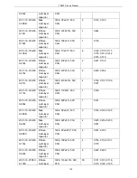
1
C109
2LL1-16-3R3K
R laminated
inductor
1608,
3.3μH±10%(MLF1608A3
2
L105, L117
141
Summary of Contents for TR850
Page 1: ......
Page 45: ...TR850 Service Manual 5 4 Connection 1 2 3 4 6 8 7 5 9 10 13 14 15 16 18 17 11 12 41 ...
Page 90: ...TR850 Service Manual Figure 1 Rx Module Top Board PCB View 86 ...
Page 91: ...TR850 Service Manual Figure 2 Rx Module Bottom Board PCB View 87 ...
Page 93: ...TR850 Service Manual Figure 5 Power Amplifier Module Bottom Board PCB View 89 ...
Page 94: ...TR850 Service Manual Figure 6 Baseband Mainboard Top Board PCB View 90 ...
Page 95: ...TR850 Service Manual Figure 7 Baseband Mainboard Bottom Board PCB View 91 ...
Page 97: ...TR850 Service Manual Figure 10 Power Board Top Board PCB View 93 ...
Page 114: ...TR850 Service Manual Figure 16 Baseband Mainbaord Schematic Diagram 110 ...
Page 169: ...TR850 Service Manual Figure 1 Rx module Top Board Position Mark Diagram 165 ...
Page 170: ...TR850 Service Manual Figure 2 Rx Module Buttom Board Position Mark Diagram 166 ...
Page 172: ...TR850 Service Manual Figure 5 Power Amplifier Module Buttom Position Mark Diagram 168 ...
Page 173: ...TR850 Service Manual Figure 6 Baseband Mainboard Top Board Position Mark Diagram 169 ...
Page 174: ...TR850 Service Manual Figure 7 Baseband Mainboard Buttom Board Position Mark Diagram 170 ...
Page 176: ...TR850 Service Manual Figure 10 Power Board Top Board Position Mark Diagram 172 ...
Page 193: ...TR850 Service Manual Figure 16 Baseband Mainboard Schematic Diagram 189 ...


