Introduction
9
DS560/DS570 User's Guide - Rev. A04
StorCase Technology, Inc.
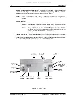
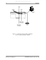
Chassis Rear Panel
(Figures 6 & 7)
NOTE:
If a module slot is to be left empty, the filler plate (provided) must be installed.
Installation of the filler panel is necessary for proper cooling inside chassis.
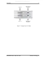
SCSI I/O Connectors
- The DS570 comes equipped with two (2) Ultra160 68-pin
HD connectors.
Host Ch. 1
- Connects to SCSI Host 1.
Host Ch. 2
- Connects to SCSI Host 2.
DB9 Connectors
- The DS570 comes equipped with two (2) DB9 serial connectors.
(RS-232)
- Connects to a VT-100/ANSI terminal via a DB9-DB9 cable (provided).
Refer to section "
Monitor Utility
" for further information.
(MODEM)
- Connects to a modem for Page/FAX notification. Refer to section
"
System Params Menu
" for further information.
Power Supply Module(s)
- Dual 400W auto-ranging power supply modules run
in Shared Mode which allows both to operate at reduced wattage and lower
operating temperature. In the event that one power supply should fail, the other will
carry the full load.
Blower Vent(s)
- Two (2) adjustable dual-speed blowers (one in each power
supply module) provide ample cooling of chassis (79 CFM Total).
Module Handle(s)
- Provide a sturdy grip for the installation and removal of the
power supply modules.
WARNING:
DO NOT USE MODULE HANDLES TO LIFT CHASSIS! These
handles are specifically designed for the installation and re-
moval of modules only!
Power Switch(es)
- Rocker switch(es) control power to the power supply
module(s).
A/C Power In
- Accepts U.S. and other available international standard power
cords.
All manuals and user guides at all-guides.com

