134
4. Go to
Label
Tab: Fill in fields to denote states.
5. Click
OK
to place the Multi-State Switch part on the window. Position the Multi-State Switch part and resize it if necessary.
Adjust the label position as desired.
Note:
Refer to Section 2: Software Reference Guide, Part Placement for details about completing each tab item.
Note:
Switch Style Functions
Set Style
Description
JOG+
The value in the designated write address is increased by one when the Multi-State
Switch is pressed.
JOG-
The value in the designated write address is decreased by one when the Multi-State
Switch is pressed.
Note:
Range is -32768 to 32767. Above 32767 the value cycles to -32768, below -32768 the value cycles to 32767.
Design Tips:
1. Use the same device address for read and write to have the Multi-State Switch show the state of the device it is
changing.
2. Use the Multi-State switch to jog through text selections. For example, states 0-6 correspond to days of the week
(Sunday through Saturday). Assign the labels of states 0-6 to correspond to the days of the week. You may or may not
use a shape for this object. This Multi-State Switch allows the operator to select the day of the week. This is useful when
setting the internal real time clock.
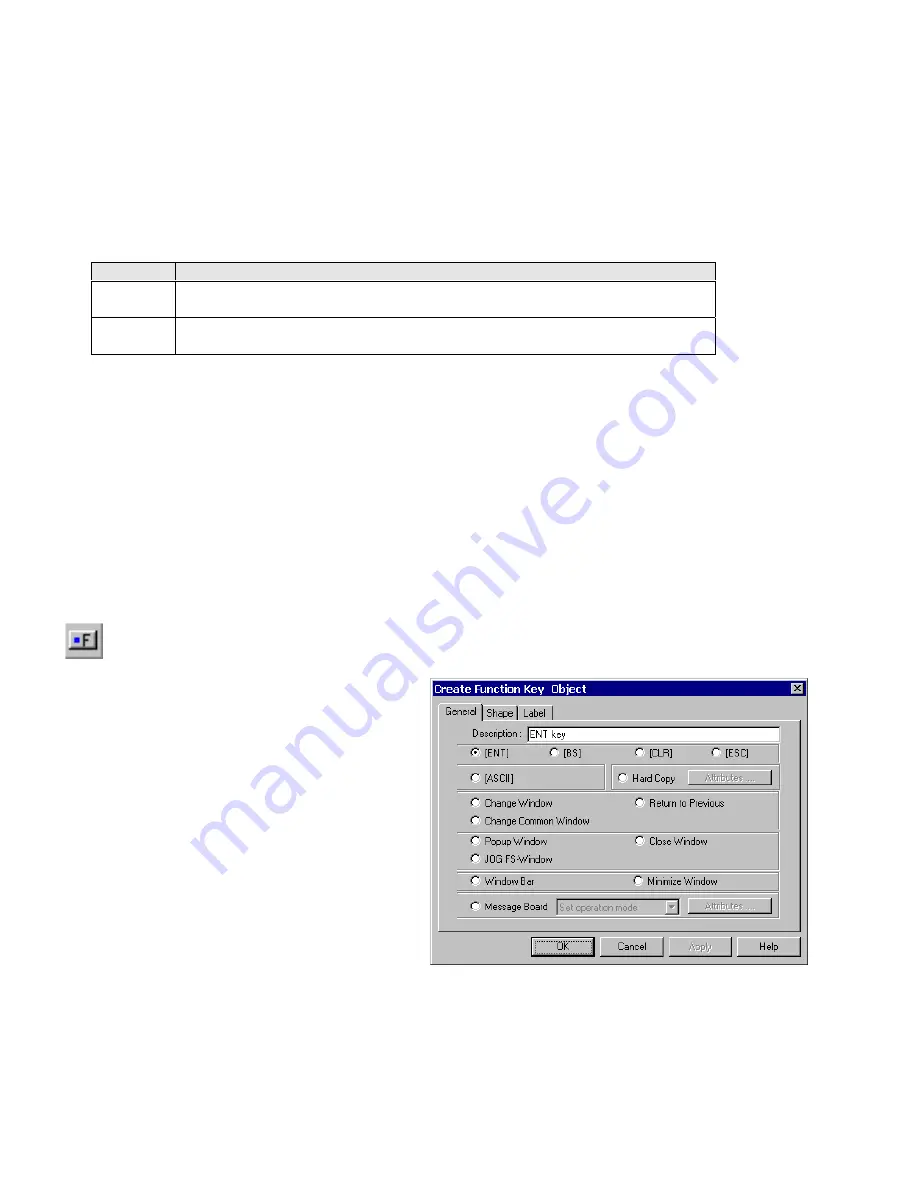
13.7 Function key
The Function Key is used to create an active screen area for a data entry key, inputting a digit or ASCII character,
changing screen displays and minimizing or moving windows.
Procedure to place a Function Key
1. Click Function Key icon or select
Function Key
from
the
Parts
menu.
2. Fill in General Tab Items:
Description
: A reference name (not displayed) that you
assign to the Function Key.
Determine what function occurs when pressed, See
options below.
3. Go to
Shape
Tab: Select Shape or Bitmap to display
states that represent the touch area.
4. Go to
Label
Tab: Fill in fields to denote states.
5. Click OK, position the Function Key and resize it if necessary.
Click
OK
to place the Function Key part on the window. Position the Function Key part and resize it if necessary. Adjust the
label position as desired.
Note:
Refer to Section 2: Software Reference Guide for details about completing each tab item
Summary of Contents for MMI-1500
Page 2: ...ii...


