4 Installation steps
FOCUS
29
8.
Attach the external exposure button to the
cable tie anchor on the control panel frame. Use
the included cable tie. Leave approx. 15
centimeters of free cable to connect the control
panel circuit board. Trim off the end of the
cable tie.
9.
Cut out the relief in the control panel cover to
create an opening for the external exposure
button cable.
10.
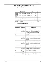
Move the DIP-switch “3” to position “OFF” on
the control panel circuit board to disable the
primary exposure button on the control panel
and enable only the external exposure button.
11.
Carefully connect the Ethernet cable to
connector X21
and the remote exposure button
cable to connector X23 pins “GND” and “2ND”.
12.
Carefully install the control panel circuit board
to the control panel frame and attach the
control panel cover using the screw at the
bottom.
13.
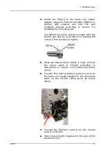
Attach the magnetic exposure button holder to
the optional electronics mounting plate on the
treatment unit and put the external exposure
button to the holder.
14.
Route the Ethernet cable to the connection box
board of the FOCUS unit and connect it to
connector X63.
Summary of Contents for FOCUS 215720
Page 2: ......
Page 4: ......
Page 6: ...ii...
Page 12: ...2 Unit description 6 FOCUS Exposure time control...
Page 55: ...6 Dimensions FOCUS 49 6 Dimensions Wide wall mount plate measures in mm...
Page 56: ...6 Dimensions 50 FOCUS Narrow wall mount plate measures in mm...
Page 57: ...6 Dimensions FOCUS 51 Remote control frame measures in mm...
Page 58: ...6 Dimensions 52 FOCUS Wall mount installation dimensions...
Page 59: ...6 Dimensions FOCUS 53...
Page 60: ...6 Dimensions 54 FOCUS...
Page 61: ...6 Dimensions FOCUS 55...
Page 62: ...6 Dimensions 56 FOCUS OpenMount installation dimensions...


