4 Installation steps
FOCUS
43
4.10.3 Converting a permanent wiring to a
non-permanent (plug)
NOTICE!
OpenMount configuration is intended for
permanent installation only.
1.
Remove the cable F32 from the fuse F3 and
from mains switch the connector. Remove also
the cable F33 (both cables blue and black) from
fuse F3, from the mains switch connector and
from the terminal block X91. Cable markings
are found on the cables.
Circuit diagram 2. Cable connections in a non-
permanently installed unit.
2.
Plug the blue cord from the cable F4 between
the fuse F2 and the connector 2 of the terminal
block X91. Plug the black cord from the cable
F4 between the fuse F3 and the connector 1 of
the terminal block X91.
3.
Plug the blue cord from the cable F3 between
the fuse F2 and mains switch connector slot,
which is on the same side as the blue cord from
the cable F52.
Summary of Contents for FOCUS 215720
Page 2: ......
Page 4: ......
Page 6: ...ii...
Page 12: ...2 Unit description 6 FOCUS Exposure time control...
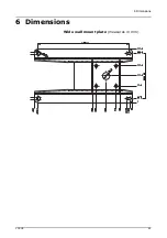
Page 55: ...6 Dimensions FOCUS 49 6 Dimensions Wide wall mount plate measures in mm...
Page 56: ...6 Dimensions 50 FOCUS Narrow wall mount plate measures in mm...
Page 57: ...6 Dimensions FOCUS 51 Remote control frame measures in mm...
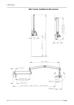
Page 58: ...6 Dimensions 52 FOCUS Wall mount installation dimensions...
Page 59: ...6 Dimensions FOCUS 53...
Page 60: ...6 Dimensions 54 FOCUS...
Page 61: ...6 Dimensions FOCUS 55...
Page 62: ...6 Dimensions 56 FOCUS OpenMount installation dimensions...


