background image

107

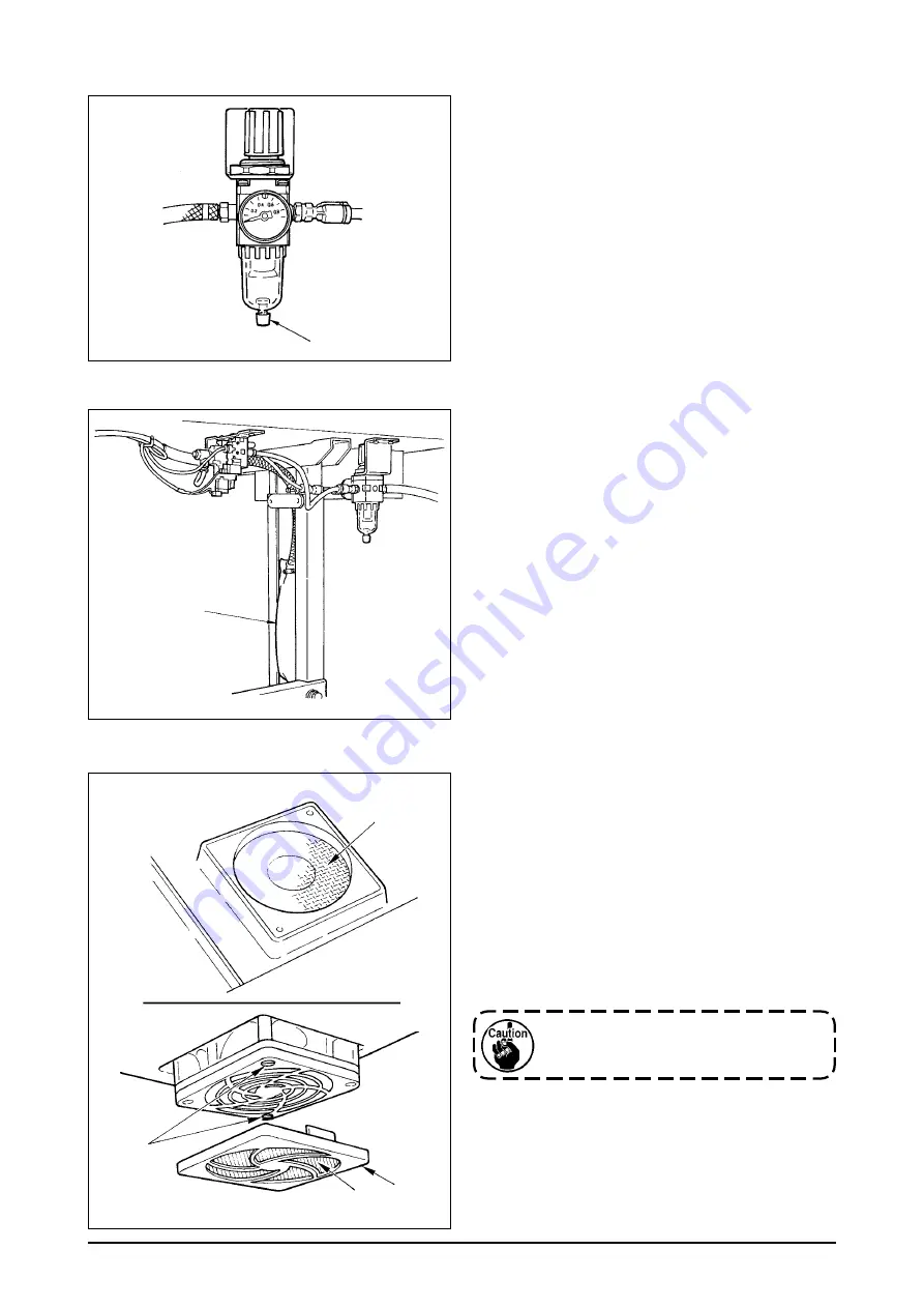
(5) Cleaning the cooling fan installed on the under cover

Cloth waste or the lke gathers around the coolng 
fan filter section installed on the lower part of the un-
der cover, and there s a case where coolng effect of 
the machne head s decreased.
When cloth waste or the lke has gathered, remove 
fan cover 

1

 and take off the cloth waste or the lke 

of flter secton 

2

. In addton, when there s cloth 

waste or the like in filter section 

3

, remove filter set-

screws 

4

 and take off the cloth waste or the lke of 

filter section 

3

.

Be sure to install filters 

2

 and 

3

 after 

they have been completely dried up. 

3

4

2

1

1

1

(3) Draining (Bird’s nest prevention (CB) type only)

When the regulator becomes filled with water, turn 
knob 

1

 for dran counterclockwse.

(4) Cleaning the dust bag (Bird’s nest prevention (CB) type only)

Perodcally clean dust bag 

1

.

  When the dust bag becomes excessively filled 

wth waste thread, there may be cases where 

clamp falure occurs.


Summary of Contents for LZ-2290A/IP-110A/SC-915

Page 1: ...ENGLISH LZ 2290A IP 110A SC 915 Instruction Manual CompactFlash TM is the registered trademark of SanDisk Corporation U S A ...

Page 2: ...titch of each shape 47 6 8 Selection of the kind of stitching 48 1 Overlapped stitching 48 2 Programmed stitching 48 6 9 Custom pattern 50 1 Custom pattern setting 50 2 New creation of the custom pattern 51 3 Custom pattern edit 52 4 Registration copy and deletion of the custom pattern 52 6 10 Condensation Custom 54 1 Condensation custom setting 54 2 Condensation custom edit 55 6 11 Pattern stitch...

Page 3: ...ANCE 106 1 Replacing the power fuse 106 2 Adjusting the contrast of the operation panel display 106 3 Draining Bird s nest prevention CB type only 107 4 Cleaning the dust bag Bird s nest prevention CB type only 107 5 Cleaning the cooling fan installed on the under cover 107 6 Cleaning the hook section 108 7 Cleaning the rear cover of the control box 108 8 Cleaning the operation panel screen 108 9 ...

Page 4: ... switch Pre tension 2Wiper switch WB CB type 0Hand switch 6Thread stand 3Thread take up cover 1Stitch length dial 7Oil supply opening 4Finger guard 2Condensation dial 8Mirror inversion switch 5Thread tension controller 3Control panel Rotary tension 4Bobbin winder 6Electrical box 7Pedal 4 3 2 4 3 5 6 2 1 7 o q t 0 i y u 8 ...

Page 5: ...LZ 2290A SU 7 Application Light weight materials to medium weight materials Max sewing speed 5 000 sti min 1 4 500 sti min 1 Max zigzag width 10 mm 2 Max feed pitch 5 mm stepless fine adjustment 2 5 mm stepless fine adjustment Stitch pattern 8 kinds 14 patterns custom pattern up to 500 stitches 20 kinds can be stored Needle SCHMETZ 438 ORGAN DPX5 65 to 90 Oil used JUKI New Defrix Oil No 1 Thread t...

Page 6: ... stitch 3 step zigzag stitch 4 step zigzag stitch Scallop right Scallop left Blind stitch right Blind stitch left Custom pattern Standard scallop Crescent scallop Equal width scallop Equal width scallop Standard scallop Crescent scallop Equal width scallop Equal width scallop Number of stitches for pattern Remarks Max zigzag width a a ...

Page 7: ... hinge 8 before placing the machine head on cushions 3 on the four corners 5 Attach head support rod 6 to the machine table However this step is not necessary for the ma chine with AK 9 device 23 5 mm 19 5 mm 1 4 A B 4 INSTALLATION 4 1 Installation of the sewing machine head WARNING Perform the installation of the sewing machine by the technical personnel who have been trained To prevent personal ...

Page 8: ...e bar stopper Remove needle bar stopper 1 for transportation Keep the needle bar stopper which has been removed and install this needle bar stopper when transporting the sew ing machine The needle bar stopper may be cut when it is strongly drawn out Slightly move the needle bar to the right or left and slowly draw out the nee dle bar stopper 4 3 Attaching the knee lifter Insert knee lifter pad 1 i...

Page 9: ... to 9 white cord to 6 black cord to 7 and red cord to 8 with screws In case of single phase power cable Put power cable from hole B of the power switch and securely fix green yellow cord to 9 and other cords to 6 and 7 with screws 8 is not used 4 Installing the power switch cover Securely tighten screw 1 located on the side of the power switch 4 7 Installing the operation panel IP 110 1 Install op...

Page 10: ...ened 4 Remove the locks of cord clamps a b c d e and f A C d a b E B D e f c 4 8 Connecting the cords WARNING To prevent personal injury caused by abrupt start of the sewing machine carry out the work after turning OFF the power switch and a lapse of 5 minutes or more To prevent damage of device caused by maloperation and wrong specifications be sure to connect all the corresponding connectors to ...

Page 11: ...nd insert it into connector CN21 6 of the circuit board at tached to the front cover 8 Insert white connector 26P cord 7 coming from the control panel inside the electrical box through front cover through hole B pass it through cord clamps b c and d insert it into connector CN34 8 and lock it 2 b B 1 3 B 4 5 6 7 8 c b d 2 Connecting the connectors Each connector has the inserting direction Check t...

Page 12: ...d clamps b c d and g and insert it into con nector CN53 4 Close cord clamps b c and d 12 Insert white connector 6P three cords 5 com ing from the machine head inside the electrical box through front cover through hole B pass it through cord clamps a and e and insert it into connector CN54 6 13 Insert white connector 10P cord 7 and blue connector 2P cord 8 coming from the machine head inside the el...

Page 13: ...ront cover through hole B coming from the foot pedal for standing work pass it through cord clamps b and c and in sert it into connector CN32 6 17 Connect white connector 2P of cord 7 sup plied as accessories to which red connector 2P and white connector 2P are attached to white connector 2P 8 of under cover of the machine head Fix omega lock 9 supplied as accessories with the neighboring cords an...

Page 14: ...ver and the electrical box main body close the rear cover while pressing section A on the lower side of the rear cover and tighten four screws 1 w Press down cord presser plate C of cord through hole B of the front cover press the cord and tighten screws 2 1 2 3 A B C 4 3 4 B A 1 2 Clamp 1 4 3 2 4 Lightly press the corner of clamp Cord clamp is locked with a click How to lock the cord clamp 4 9 At...

Page 15: ...6 and ø8 hoses attached to regulator total asm 3 to the respective solenoid valves 5 Insert dust bag 5 into the top end of hose 9 for dust bag and fix it with band 6 supplied with the sewing machine as accessories 4 12 Installing the bird s nest prevention CB type sewing machine 1 2 4 3 6 5 9 5 9 1 2 4 11 Installing the thread stand 1 Assemble the thread stand unit and insert it in the hole in the...

Page 16: ... 7 Connect air hose ø4 coming from the machine head to the solenoid valve section and air hose ø8 to the dust bag suction port respectively 8 Fix the solenoid valve and the air hose on the table with staple 8 supplied as accessories 3 2 2 1 Upper engraved marker line 4 13 Lubrication LZ 2290A SS A SU 7 WARNING 1 Do not connect the power plug until the lubrication has been completed so as to preven...

Page 17: ...resser foot will go up D Further depress the back part of the pedal and the thread trimmer will be actuated A B D E C 4 14 Test run 1 Turn ON the power 1 When the needle bar is in its UP position zigzag origin detection is performed 2 When the needle bar is in the position other than UP position Display as shown in the figure below appears Turn the handwheel to bring the needle bar to needle UP po...

Page 18: ...sen the needle clamp screw 2 Hold the nee dle 1 so that the long groove B on the needle is facing exactly toward you 3 Insert the needle deep into the hole of the needle bar in the direction of the arrow until it will go no further 4 Securely tighten the screw 2 5 Confirm that the long groove B on the needle faces toward you 5 PREPARATION BEFORE SEWING WARNING To protect against possible personal ...

Page 19: ...e center of the bobbin is as high as the center of the thread tension disk Move the position of the thread tension disk 2 to the direction A as shown in the figure on the left when the winding amount of the bobbin thread on the lower part of the bobbin is excessive and to the direction B as shown in the figure on the left when the winding amount of the bobbin thread on the upper part of the bobbin...

Page 20: ... of to reduce the reverse feed stitch length Example When stitch length dial 1 is used with the graduation of 2 the maximum adjustment value of condensation stitching adjusting dial 3 be comes 2 It is possible to adjust within the range of 2 to 2 Maximum feed amount is regulated to 2 according to the gauge delivered feed dog 22581508 Adjustment can be performed up to the range of maximum 5 to 4 by...

Page 21: ...s not provided with automatic reverse feed stitching device For the details see p 42 This is the switch to turn ON OFF automatic reverse feed stitch at sew ing end This switch cannot be used with the sewing machine which is not provided with automatic reverse feed stitching device For the details see p 42 This is the switch to make the value of bobbin thread counter or sewing counter the set value...

Page 22: ...witch cannot be used with the sewing machine which is not provided with the automatic thread trimming device This is the switch to set the value of bobbin thread counter or No of pcs counter When moving the resistor in the left direction max speed is lim ited This lamp lights up when the power switch is turned ON This is the cover for media inserting opening To open the cover place your finger on ...

Page 23: ...aller than the specified value it is in danger of causing the needle to be broken or the like 1 Limitation of the max zigzag width Max zigzag width can be limited in accordance with the gauge There are two kinds of limitations of max zigzag width 1 Zigzag width symmetrical in the center 2 Specifying left right positions Changeover of limiting procedure of max zigzag width limitation value 2 Specif...

Page 24: ... screen returns to the previous one Change of left side posi tion limitation 1 Press of switch 5 to set the left side limitation value In case of the example set the value to 3 3 Change of right side posi tion limitation 2 Press of switch 6 to set the right side limita tion value In case of the example set the value to 4 7 3 Press switch 1 and the screen returns to the previous one Limitation of z...

Page 25: ...very time switch 3 is pressed reference of left stitch base line that of right stitch base line and that of center stitch base line are changed over and set alter nately 4 Press switch 1 and the screen returns to the previous one Reference of left stitch base line Reference of center stitch base line Reference of right stitch base line Reference of left stitch base line Reference of center stitch ...

Page 26: ...ontents of display change depending on the set values Sewing shape list first screen Selection of each shape is performed Sewing shape setting screen Setting of zigzag width position of stitch base line etc is performed Reverse feed stitching setting screen Setting of kind of condensation number of stitches etc is performed When is pressed for approximately three seconds in a screen other than the...

Page 27: ...titching Left equal 12 stitches Left equal 24 stitches Left standard Left crescent Right equal 12 stitches Right equal 24 stitches Right standard Right crescent 6 4 List of the display pictographs of each screen Sewing shape list first screen Sewing shape list second screen Scallop selection pop up screen 4 step zigzag stitch ...

Page 28: ...n Cycle stitching new creation Blind stitch selection pop up screen The key lock level has been set to 1 at the time of delivery and pictographs of new creation are not dis played When performing new creation in each mode change the key lock level to 0 Refer to the second screen of sewing common data setting of 1 Sewing common data of 6 15 Information In addition the display of pattern No at the t...

Page 29: ...g Overlapped stitching Kind of sewing Position of stitch base line Programmed stitching Pattern register 5 0 to 5 0 Kind of sewing Free stitching Overlapped stitching Programmed stitching Zigzag width Position of stitch base line Position at sewing start Position at sewing end Pattern register 5 0 to 5 0 0 to 10 0 Optional Right Left Optional Right Left ...

Page 30: ...end is optional Kind of sewing Zigzag width Position of stitch base line Position at sewing start Root Crest Position at sewing end Root Crest Stop position Free stitching Overlapped stitching Programmed stitching Pattern register 5 0 to 5 0 0 to 10 0 Root Crest Optional Right Left Optional Root ...

Page 31: ...Free stitching Overlapped stitching Programmed stitching Free stitching Overlapped stitching Programmed stitching Pattern register Kind of sewing Zigzag width Position of stitch base line 5 0 to 5 0 0 to 10 0 3 to 250 5 0 to 5 0 0 to 10 0 Edit screen display Custom pattern needle entry image Pattern register Copy and deletion screen Pattern register Copy Deletion ...

Page 32: ...d stitch Right and Left Custom 1 to 20 Free stitching Overlapped stitching Sewing shape Kind of sewing Display of contents depends on shape Refer to each shape Copy and deletion screen Copy Deletion Step Zigzag position input Feed direction Normal Reverse Custom pattern needle entry image Needle entry point insertion Needle entry point delection Determination Last needle entry input Normal Reverse...

Page 33: ...ern is displayed Number of stitches cannot be set to 0 Determination switch prohibition 0 0 to 10 0 5 0 to 5 0 1 to 20 Zigzag width Position of stitch base line Step Pattern No Number of stitches Edit screen display Copy and deletion screen Copy Deletion Step Pattern No Number of stitches Sewing shape 1 to 20 1 to 99 Determination 0 to 500 ...

Page 34: ...ion of presser foot is displayed except the case where the number of stitches is 0 stitch with the auto lifter Presser lifting time is displayed when the position of presser foot is UP stop Step Pattern No Num ber of stitches Stop state Position of press er foot Edit screen display Copy and deletion screen Copy Deletion Step No Num ber of stitches Stop state Position of presser foot Presser liftin...

Page 35: ...thout Sewing start Sewing end Selection of kind Process A Process B Selection of kind Process C Process D Reverse stitching at sewing start With without Normal 0 to 19 0 to 19 Normal 0 to 19 0 to 19 Custom Custom 2 point 0 to 19 0 to 19 2 point 0 to 19 0 to 19 Width adjustment at sewing start Width adjustment at sewing end 0 0 to 5 0 0 0 to 5 0 ...

Page 36: ...f max zigzag width limitation is set to Left Right the display of max zigzag width limitation value is separately indicated left and right 0 0 to 10 0 0 0 to 10 0 Width adjustment at sewing start Width adjustment at sewing end 0 0 to 10 0 Reference of stitch base line Limiting procedure of max zigzag width limitation Max zigzag width limitation value Center Center Left Right Left Right ...

Page 37: ...tion value becomes that of symmetrical in the center 0 0 to 10 0 Center Left Right Left Right Center 0 0 to 10 0 Limiting procedure of max zigzag width limitation Specify ing left position Specify ing right position Reference of stitch base line Conden sation cus tom stitch base line Mirror function setting Counter function Key lock Max zigzag width limitation when turning ON the power 1 pattern C...

Page 38: ...NING Be sure to check presser foot and gauge currently being used before sewing after changing the zig zag pattern or zigzag width In case where sewing is performed with the presser foot or gauge not matching the zigzag width it is in danger of accident such as needle breakage or the like Determined pattern 1 Select the zigzag pattern you desire to sew with the selection switch when the figure abo...

Page 39: ...dth scallop of 24 stitches Left equal width scallop of 12 stitches Right standard scallop Right crescent scallop Determined pattern Left blind stitch Right blind stitch Right equal width scallop of 24 Right equal width scallop of 12 Determined pattern In case of the blind stitch 1 Press the blind stitch key and the screen on the left side appears Press the pattern switch you desire to select 2 As ...

Page 40: ...start Set the position of sewing start with of switch 6 Setting of the stop position Set the stop position with of switch 7 1 2 step zigzag 3 step zigzag and 4 step zigzag stitch Sewing shape list first screen 1 Select 2 step 3 step or 4 step zigzag stitch in the sewing shape list first screen 2 The selected shape reverses and is displayed on the left end of the screen 3 Press to display the sewin...

Page 41: ...reen 2 Press the switch of pattern to be selected from the screen of the left figure 3 The selected shape reverses and is indi cated on the left end of the screen 4 Press to display the sewing shape set ting screen Setting of the zigzag width Change the zigzag width with of switch 1 Setting of the position of stitch base line Change the position of stitch base line with of switch 2 Right equal wid...

Page 42: ...ional Stop position right Stop position left Setting of the stop position Set the stop position with of switch 5 Stop position optional Stop position root Start from crest and start from root of scallop Start from crest Start from root Normally scallop starts the sewing with the pat tern of start from root However start from crest can be selected by chang ing the setting Start of sewing Needle pos...

Page 43: ...ion of stitch base line with of switch 2 Change of the number of stitches Change the number of stitches with switch 3 3 Blind stitch sewing Sewing shape list first screen 1 Select the blind stitch sewing in the sewing shape list first screen 2 Press the switch of pattern to be selected from the screen of the left figure 3 The selected shape reverses and is indi cated on the left end of the screen ...

Page 44: ...ion of stitch base line with of switch 2 4 Custom pattern stitching Sewing shape list first screen Custom pattern selection pop up screen h h 1 Select custom pattern 1 in the sewing shape list first screen 2 Press the custom pat tern No to be select ed 3 The selected shape reverses and is indi cated on the left end of the screen 4 Press to display the sewing shape set ting screen q w 1 w q ...

Page 45: ...n be set by pressing reverse feed stitch at sewing start switch 1 and reverse feed stitch at sewing end switch 2 In case the reverse feed stitching is effective the respec tive shapes of the reverse feed stitching are displayed In case of ineffective the shape is not displayed For the reverse feed stitching there are standard condensation 2 point condensation and condensation custom 6 7 Reverse fe...

Page 46: ...tting screen 2 Set the shape of condensation and number of stitches 1 Select the shape of condensation at the sewing start 2 Set the number of stitches of process A with and 3 Set the number of stitches of process B with and 4 Select the shape of condensation at the sewing end 5 Set the number of stitches of process C with and 6 Set the number of stitches of process D with and Display section of 1...

Page 47: ...ondensation 2 point condensation performs reverse feed stitching of two points between the existing needle entry of the selected zigzag pattern and the next needle entry The width between two points can be adjusted in the direction of Example Reverse feed stitching at sewing end Example In case of free stitching of the standard zigzag stitch 1 Press to display reverse feed stitching setting screen...

Page 48: ... needle entry position to the next needle entry position when performing the reverse feed stitching When set value is 0 there is no com pensation When the width adjustment is performed the width between 2 points can be narrowed and the fray of thread is lessened The first screen of reverse feed stitching setting 2 point condensation Press to display the second screen Press to display the first scr...

Page 49: ...d stitching setting condensation custom 3 Condensation custom Condensation custom performs reverse feed stitching with the optional needle entry which has been input ted 1 Select the shape of condensation with the first screen 1 Select the shape of condensation at the sewing start 3 Select the shape of condensation at the sewing end 2 4 Needle entry position is displayed 2 Set the width of condens...

Page 50: ...ondensation Sewing start Sewing end Condensation custom Sewing start Sewing end Straight stitch 2 step zigzag stitch 3 step zigzag stitch 4 step zigzag stitch Scallop Blind stitch Custom Continuous stitch 4 Comparison table of the reverse stitch of each shape ...

Page 51: ...specified number of times of normal and reverse feed stitching performs automatic thread trimming and stops Turn ON the thread trimming prohibition switch ON when you desire to stop the sewing machine with needle UP position without performing thread trimming after all processes have been completed Thread trimming is performed at any occasion in case of one shot stitching and the last of process T...

Page 52: ...0 steps and programmed stitching selection screen of 11 to 20 is displayed Press and the screen returns to programmed stitching selection screen of 01 to 10 1 Select showing pro grammed stitching with 1 of sewing shape setting screen When automatic thread trimming is selected 0 is not displayed in the last step When increasing the number of steps proceed to the next step after releasing automatic ...

Page 53: ...he step is completed Teaching screen One shot automatic stitching One shot automatic stitching can be set by each step 1 In the programmed stitching edit screen press one shot automatic stitching switch 5 to select the one shot automatic stitching When it is in the selected state a mark is displayed on the side of switch 5 2 In the step where the one shot automatic stitching has been selected the ...

Page 54: ...g the inputted left and right positions as reference 5 Set the position of stitch base line with and 6 Needle entry position is displayed 2 New creation of the custom pattern Custom pattern is newly created New creation pop up screen 1 Press in the custom pattern selection pop up screen to display the new creation pop up screen 2 Nos which have not been registered at present are displayed in 1 Sel...

Page 55: ...not possible to insert it when the number of total stitches is 500 stitches 2 Delete one stitch of the needle entry of the existing step Then the stitches move forward one stitch by one stitch It is not possible to delete it when the number of total stitches is 1 stitch 3 When setting is completed up to the last step proceed to the next step press 3 and put END mark When the number of stitches of ...

Page 56: ... is in the selective state How to copy Copy pop up screen 1 Press 2 in the pop up screen of registration copy and deletion of custom pattern 2 Copy pop up screen is displayed 5 Select the custom pattern of copy source with and It is possible to select only No which has been registered 6 Select the custom pattern of copy destination with and It is possible to select only No which has been not regis...

Page 57: ...n the reverse feed stitching screen 1 Select the shape of condensation at sewing start from among 1 to 20 Standard condensation 2 point condensation and condensation customs to are changed over and displayed in the display section 3 Select the shape of condensation at sewing end from among 1 to 20 Standard condensation 2 point condensation and condensation customs to are changed over and displayed...

Page 58: ...dle entry of the existing step Then the stitches move forward one stitch by one stitch It is not possible to delete it when the number of total stitches is 1 stitch 4 When setting up to the last step is completed proceed to the next step press 6 and put END mark When the last step is 64 it is not necessary to set END mark 5 When all inputting procedures have been completed press key to determine T...

Page 59: ... the sewing shape list 6 11 Pattern stitching Pattern selection pop up screen 1 Select 1 in the second screen of the sewing shape list 2 Press switch 2 corre sponding to the sew ing which has been registered or the pat tern you desire to edit in the pattern selec tion pop up screen 3 Press to display the sewing shape set ting screen When the power source is turned OFF without pressing key the inpu...

Page 60: ...m 2 Registering the pattern stitching It is possible to register at the time of free stitching and overlapped stitching Select in advance the shape you desire to register from the sewing shape list screen 1 Press to display the sewing shape setting screen 2 Press 1 to display the new registration pop up screen in the sewing shape setting screen Example Scallop stitching Sewing shape setting screen...

Page 61: ...n Then copy and deletion of the pattern stitching can be performed How to copy Copy and deletion pop up screen 1 Press 1 in the copy and deletion pop up screen to display the copy pop up screen 3 Select pattern No of the copy source with and Registered Nos only can be selected 4 Select pattern No of the copy destination with and Non registered Nos only can be se lected When is pressed here the scr...

Page 62: ...inuous stitching can sew the different zigzag patterns in combination Changeover of the respective patterns can be set with the number of stitches Continuous stitching can combine as many as 20 steps and 500 stitches per step can be set In addition up to 10 patterns can be registered To perform the continuous stitching it is necessary to register in advance the pattern to be used in each step Exam...

Page 63: ... continuous stitching Continuous stitching pattern can be newly created New creation pop up screen 1 Press in the continuous stitching selection pop up screen to display the new creation pop up screen 2 Nos which have not been registered at present are displayed in 1 Select the No you desire to obtain with and When is pressed here the screen returns to the former one without creating the pattern 3...

Page 64: ...inuous stitching edit screen Continuous stitching edit screen 6 Select the pattern and set the number of stitches in each step in the continuous stitching edit screen 8 Set the step with and As many as 20 steps can be set 9 Set the pattern No with and Registered pattern only can be set 0 Sewing shape of the pattern which has been selected at 9 is displayed 1 Set the number of stitches with and As ...

Page 65: ...opy destination is in the selective state after copy has been performed Copy pop up screen How to delete Deletion pop up screen 1 Press 2 in the copy and deletion of continuous stitching pop up screen 2 The deletion pop up screen is displayed 5 Select the continuous stitching pattern to be deleted with and When is pressed here the screen returns to the former one without performing deletion 3 When...

Page 66: ...g to the registered sewing or patterns you desire to edit in the cycle stitching selection pop up screen 3 Press to display the cycle stitching setting screen 2 Cycle stitching edit The second screen of sewing shape list 1 Press in the cycle stitching selection pop up screen to display the new creation pop up screen 2 Nos which have not registered at present are displayed in 1 Select the No you de...

Page 67: ...ess to display the cycle stitching edit screen 6 Set pattern No number of stitches stop position and position of the presser for each step in the cycle stitching edit screen 8 Set the step with and As many as 20 steps can be set 9 Select pattern No with and Pattern Nos to which patterns have been registered only can be set 0 Set the number of stitches with and As many as 500 stitches can be set 1 ...

Page 68: ...registered When is pressed here the screen returns to the former one without performing copy 3 When is pressed copy is performed The No which is selected to the copy destination is in the se lective state after copy has been performed 3 Copy and deletion of the cycle stitching Press in the cycle stitching setting screen to display the copy and deletion of cycle stitching pop up screen Then copy an...

Page 69: ... on the way or perform re sewing 4 Teaching Teaching can input the number of stitches of inputting step with the number of stitches which has been actually sewn 1 Press switch in the cycle stitching edit screen and the teaching mode is obtained 2 Depress the front part of the pedal to sew until the last stitch of the step is reached At this time input of the number of stitches cannot be performed ...

Page 70: ...performed by setting the number of stitches in the cycle stitching Example In the process of label attaching change over the zigzag patterns of constant dimension stitching of 2 step zigzag stitch and straight stitch as shown in the figure and perform the constant dimension stitching 1 Register in advance the 2 step zigzag stitch for the shape of pattern 1 and the straight stitch for the shape of ...

Page 71: ... in accordance with the thickness of cloth or sewing speed Adjust the counter in accordance with the sewing conditions Bobbin thread replacement warning pop up 1 Turn ON the power When the needle bar is not in the UP position turn the handwheel to bring the needle bar to its UP position 2 Press switch 1 to display the information screen Information screen operator level 2 Set the initial value wit...

Page 72: ...ion there are two settings below q w e q w e r t y r t y u u i i 1 Limiting procedure of max zigzag width limitation For the limiting procedure of max zigzag width limitation there are two settings below 1 Center 2 Left right 2 Max zigzag width limitation value Display varies according to the procedure selected in 1 1 When the center is set in 1 Max zigzag width limitation value center 2 When the ...

Page 73: ...me the setting switch is pressed display non display is changed over alternately 1 Display 2 Non display Level of the standard delivery is 1 When changing the locked contents of level 1 it is necessary to set the level to Level 0 once 5 Position of the stitch base line of condensation custom The mode is the operation mode in terms of the stitch base line of condensation custom when the reference o...

Page 74: ...nformed every 1 600 thousand stitches Time of replacement of needle is informed after 100 thousand stitches 2 Sewing management information For the sewing management information there are warning of time of replacement of needle that of time of cleaning and that of time of replacement of oil as the maintenance management information Maintenance management function Sewing management information scr...

Page 75: ...elf cannot be cleared In case of the replacement of needle the warning screen is displayed at intervals of 10 minutes until clearing is performed In case of other warnings the warning screen is displayed at the time of turning ON the power until the counter is cleared 2 When 2 is pressed the screen is cleared and the counter value is cleared as well From this time counting starts newly Setting of ...

Page 76: ...h 2 Setting time inputted is shown in reverse video at 4 Sewing management information selection screen In case of stopping the warning function set the set value to 0 It is possible to individually set replacement of needle cleaning and replacement of oil respectively In case of stopping all set 0 to each Initial value of warning setting time 1 Time of replacement of needle 0 thousand stitches k ...

Page 77: ... SU 1 Maintenance personnel level 1 Turn ON the power When the needle bar is not in the UP position turn the handwheel to bring the needle bar to its UP position 2 Press switch 1 for approximately three seconds to display the information screen 2 Ver display For the details refer to the Engineer s Manual 3 Sewing common data 4 Function setting Refer to 6 16 Function setting procedure 5 Sewing mana...

Page 78: ...d 3 Selection of communication method Press 2 in the communication setting screen to display the communication method setting screen Explanation of the pictograph Parameter data Vector form data Press 7 and determine with 8 after selecting the parameter Communication method which is selected at present is shown in reverse video Data selection screen A Down load from the media B Download from SU 1 ...

Page 79: ...Screen display when file No 070 and custom pattern No 10 are selected 4 Selection of file No of the media File No input screen Press 3 in the communication setting screen to display the file No of media input screen Input the file No of media with 1 The file No which has been inputted is displayed in The No is determined with 2 after inputting the file No As the file No of the example is 070 input...

Page 80: ... the communication method setting screen refer to p 75 Press 9 in the communication setting method screen and press 0 to determine after selecting upload from the media 4 Setting of the custom pattern No Press 3 and 4 in the communication setting screen upload to set the custom pattern No 5 Selection of the file No of the media Press 5 in the communication setting screen upload to display the file...

Page 81: ...ch 2 for ap proximately three sec onds 4 This screen is the func tion setting screen Change the setting No with Key of switch 3 For the details of setting No see P 81 Example Changing the flicker reducing function Setting No 5 Change the setting No to 5 with Key of switch 3 in the figure above Press switch 4 Setting No Set value There are two kinds of function settings Level 1 and Level 2 Level 1 ...

Page 82: ... is acceptable press switch 7 When you desire to return the value to the previous one press switch 6 Turn OFF the power switch and turn ON the power switch after ap proximately one second Change of the set value is determined by turning OFF the power switch 1 Press switch 1 for ap proximately three sec onds 2 Press switch 2 t t y u w q ...

Page 83: ...eed stitching Setting No 8 Change the setting No to 8 with Key of switch 3 in the figure above Press switch 4 Change the set value with Key of switch 5 Set value has been changed from 1350 to 1250 When this changed value is acceptable press switch 7 Press switch 6 when you desire to return the value to the former one Press switch 8 in case of sewing Setting No Set value r e e i t t y u ...

Page 84: ...ng stitching 7 No function 8 Pedal neutral presser lifting function selection Do not set to 2 3 and 7 If these numbers are set trouble or accident will be caused Function of prohibiting start of the sewing machine by bobbin thread counter After thread trimming 0 When counting is out 1 or less function of prohibiting start of the sewing is not operative 1 When counting is out 1 or less function of ...

Page 85: ...of reverse feed stitching on the way is not operative 1 Automatic thread trimming after completion of reverse feed stitching on the way is performed Lowest speed by pedal Thread trimming speed Sewing speed at the start of sewing soft start Setting of number of revolution at the time of one shot automatic sewing Position where the sewing machine starts rotating from pedal neutral position Pedal str...

Page 86: ...ing 1 Provided with the function of reverse revolution to lift the needle after thread trimming Function of holding predetermined upper lower position of the needle bar 0 Not provided with the function of holding predetermined upper lower position of the needle bar 1 Provided with the function of holding predetermined upper lower position of the needle bar This function can specify the sewing spee...

Page 87: ... compensation function is ineffective 1 Pedal sensor neutral compensation function is effective 2 2 2 2 2 2 2 2 2 2 2 76 84 87 89 91 92 93 96 100 101 103 1 0 40 to 300 0 1 2 1 0 1 0 1 0 1 0 50 to MAX 0 to 9 1 0 1 0 F SCS 0 T PUT 100 F PCS 0 TRS 1 F PMAT 1 F DSBT 0 F MADF 0 S MAX 4000 F THLS 0 F MAC 0 F ANP 0 90 90 90 91 91 0 2 1 Number of rotations Pedal stroke Function to select the start up spee...

Page 88: ...tive the function will work Setting range 0 to 8 0 Flicker reducing function does not work to 8 Flickering is effectively reduced The more effective the flicker reducing function works the more the set value is made the lower the start up speed of the sewing machine will become 3 Setting of the needle bar stop position when the sewing machine stops Function setting No 10 NPS The position of the ne...

Page 89: ...trouble or accident will be caused 6 Neutral automatic presser lifting function with AK device only Function setting No 21 N NPL This function can automatically lift the presser foot when the pedal is in the neutral position Automatic lifting time of the pedal depends on the automatic lifting time after thread trimming and when the presser foot is automatically lowered it is automatically lifted a...

Page 90: ...essing front part of the pedal reverse feed stitching as many as the number of stitches specified by the function setting No 31 can be performed When operating touch back switch at the time of depressing front part of the pedal automatic thread trimming is performed after reverse feed stitching as many as the number of stitches specified by the function setting No 31 has been performed When operat...

Page 91: ...h is regarded as 0 compensation is possible by 360 1 stitch in front and in the rear 360 180 0 180 360 2 Compensation of off timing of solenoid for reverse feed stitching at the start of sewing Function setting No 52 Off timing of solenoid for reverse feed stitching at the start of sewing can be compensated in the increments of 10 Adjusting range 36 to 36 1 10 3 Compensation of off timing of solen...

Page 92: ...itching at the start of sewing 1 Foot lift function after thread trimming Function setting No 55 FLAT This function can automatically lift the presser foot after thread trimming This function is effective only when it is used in combination with the AK device 0 off Function of automatically lifting the presser foot is not provided Presser foot does not automatically go up after thread trimming 1 o...

Page 93: ... this function makes the needle pierce in the material with ease 0 Normal 1 Retry function is provided 0 Function to select the start up speed of the sewing machine Function setting No 76 F SCS This function is selected in the case where the speed of the sewing machine is desired to be more at the time of start up Time required to start is shortened by approximately 10 0 Normal curve 1 More sharp ...

Page 94: ...ensating stitching operation 1 One stitch compensating stitching operation upper stop ıî upper stop is performed only when aforementioned changeover is made 3 Setting of max number of rotation of the sewing machine head Function setting No 96 S MAX This function can set the max number of rotation of the sewing machine head you desire to use Upper limit of the set value varies in accordance with th...

Page 95: ...disc 3 slips there is a possibility that the thread tension disc felt 5 has been consumed Replace the felt with new one Part No 22528509 x 4 pcs 2 Adjusting the thread take up spring 1 To change the tension of the thread take up spring firmly tighten the screw 1 which fastens the tension post socket to the ma chine arm and insert the blade of a screwdriver into the slot in the tension post 2 to ad...

Page 96: ... the switch lever and the machine will im mediately run in the normal direction 4 Reverse feed switch 1 can be used in two posi tions by turning it For the types other than WB CB and 0B touch back kit separately sold Part No 40010795 is necessary WARNING To protect against possible personal injury due to abrupt start of the machine be sure to start the following work after turning the power off an...

Page 97: ...e auxiliary thread take up lever When reverse feed switch 4 is low according to the process adjust the height 4 Loosen setscrew 1 to remove mirror SW 2 5 Put the click of reverse feed switch 4 in the groove of installing base 6 6 Fix reverse feed switch 4 with guide 5 and setscrew 3 7 Put mirror SW 2 in installing base 6 and fix it with setscrew 1 Put mirror SW 2 in installing base 6 so that the i...

Page 98: ... refer to the mirror function setting p 69 4 For the adjustment of the height see p 93 Sewing procedure Scallop 1 Stop the sewing machine at the position you desire to perform mirror inversion during sewing 2 Press the mirror inversion switch 2 When the mirror inversion switch is received LED lights up The switch can receive only when the sewing machine stops and dose not receive when the sewing m...

Page 99: ...ightened state In addition when the amount of oil in the hook is not obtained unless oil amount adjustment screw 1 is near in fully tightened state it is considered that hook shaft oil wick JUKI Part No 11015906 is clogged or the like Replace the hook shaft oil wick For the replacing procedure refer to 10 Re placing the hook shaft oil wick of 9 MAIN TENANCE WARNING Turn OFF the power before starti...

Page 100: ... described below 1 Loosen the setscrew 1 in the presser foot micro lifter 2 Turn the presser foot micro lifting screw 2 clock wise through the hole in the face plate until the presser foot is raised as desired Then tighten the screw 1 If you do not use the micro lifting mech anism of the presser foot fully return the presser foot micro lifting screw 2 to its home position The standard of lifting a...

Page 101: ...e of the throat plate 2 1 3 2 3 3 4 2 Standard position 1 1 2mm WARNING To protect against possible personal injury due to abrupt start of the machine be sure to start the following work after turning the power off and ascertaining that the motor is at rest 8 5 Height and inclination of the feed dog Throat plate spacer part No 22503908 Feed bar spacer part No 10025906 To secure a space 2 LZ2290A U...

Page 102: ...ag stitch 5 Changeover of straight stitch and 2 step zigzag stitch can be performed 6 Zigzag width is set with and Initial value is set to 8 mm 7 Position of stitch base line is set with and 1 Turn ON the power When the needle bar is not in the UP position turn the handwheel to bring the needle bar to its UP position 2 Press switch 1 for approximately three seconds to display the information scree...

Page 103: ...g machine does not work even when the front part of the pedal is depressed during the hook adjust ing mode Needle throwing works by turning the handwheel by hand Needle bar moves when the set value is changed at needle UP position Hook adjusting mode setting screen 2 step zigzag stitch 1 2 4 A B 3 WARNING To protect against possible personal injury due to abrupt start of the machine be sure to sta...

Page 104: ...ook with a new one be sure to adjust the position of the needle guard 8 8 Adjusting height of the needle bar 1 Set the zigzag width to 0 Bring the needle to the center of the zigzag stroke 2 Remove the presser foot throat plate semicircle plate and feed dog 3 Place a semicircle plate on the plane to which the throat plate is to be attached of the bed Loosen setscrew 2 and adjust so that from the t...

Page 105: ...w 2 and adjust the low est stop position of the needle by moving the screw 2 within the slot Move the screw in the direction A to advance the timing to make the needle stop or in the direction B to retard it Do not adjust screw 2 It has been factory adjusted at the time of delivery and needle sway will be caused if it is adjusted When the gauge size which is more than that delivered as standard or...

Page 106: ... so that a distance of C 8 to 12 mm is provided between the top end of feeding wire 3 and the guide portion of thread take up thread guide A 4 and tighten screw 1 At this time leave a space of 0 5 to 1 mm between the feeding wire and the top surface of the thread take up thread guide A 3 Finely adjust with setscrews 5 so that the top end of the feeding wire is placed approximately in the center A ...

Page 107: ...by the ratchet when going and the position where the wiper returns to its home position is in the center of needle or the position exceeding the center of needle Besides adjust with wiper setscrew 5 so that when wiper 3 comes to the position of the center of nee dle when returning the clearance between the wiper and the needle tip should be approximately 2 mm and that between the wiper and the sid...

Page 108: ... 1 Then replace the knife When replacing knife 4 ceramic be careful of the injury to the fin gers When replacing knife 4 ceramic be careful of its direction and posi tion It should be almost parallel to knife fixing plate 1 Needle thread clamp ratio when needle does not enter the cloth excessively drops in comparison with that when needle enters the cloth Be sure to operate the wiper on the cloth ...

Page 109: ... slowly remove the rear cover 4 Hold the glass portion of the fuse to be replaced and remove the fuse 5 Use the fuse with the specified capacity 1 2A 250V Time lag type HF0078020P0 2 10A 250V Time lag type HF001301000 WARNING To prevent personal injuries caused by electric shock hazards or abrupt start of the sewing machine carry out the work after turning OFF the power switch and ascertaining tha...

Page 110: ...In addition when there is cloth waste or the like in filter section 3 remove filter set screws 4 and take off the cloth waste or the like of filter section 3 Be sure to install filters 2 and 3 after they have been completely dried up 3 4 2 1 1 1 3 Draining Bird s nest prevention CB type only When the regulator becomes filled with water turn knob 1 for drain counterclockwise 4 Cleaning the dust bag...

Page 111: ...of which is L shaped to the groove section of hook shaft oil wick screw 2 turn the handwheel in the normal direction of rota tion by hand and draw out the screw 2 Draw out hook shaft oil wick 1 from hook shaft oil wick screw 2 which has been drawn out and push a new hook shaft oil wick 1 JUKI Part No 11015906 to hook shaft oil wick screw 2 JUKI Part No B1808552000 At this time be sure to check tha...

Page 112: ... spring pressure of pedal the neutral position may be slipped In case the screw of handwheel of the machine is forgotten to be tightened when adjusting the stop position of needle Auto lifter function is set to OFF Pedal type is set to KFL Cord of auto lifter is not connected to connector Presser foot is lifting by means of auto lifter Auto lifter function is set to ON although auto lifter is not ...

Page 113: ...d remove the cause of error after erasing the error screen Example E499 Max zigzag width limi tation error Press the reset switch 3 Remove the cause of error after turning OFF the power 11 ERROR DISPLAY Error is informed by means of the panel display machine head mirror LED blink and control box buzzer Three different kinds of screens of the panel display screen appear due to the difference of the...

Page 114: ... 012 Read error Data read from media is not possible Turn OFF the power 013 Write error Data write to media is not possible Turn OFF the power 015 Format error Formatting cannot be performed Turn OFF the power 016 External media capacity over Capacity of media is short Turn OFF the power 019 File size over File is too big Turn OFF the power 024 Pattern data size over Number of stitches and data am...

Page 115: ...e power Consist system versions with each other 730 Encoder failure When the motor signal is not properly inputted Check the motor signal connector CN38 for loose connection and disconnection Check whether the motor signal cord has broken since the cord is caught in the machine head or the like broken since the cord is caught in the machine head or the like 731 Media not inserted 810 Solenoid shor...

Page 116: ...nformation p 71 A203 Press to close warning screen and perform replacement of needle Then clear the value in the clear screen Press to clear the value and perform replacement of needle Press to close warning screen and perform cleaning Then clear the value in the clear screen Press to clear the value and perform cleaning Press to close warning screen and perform replacement of oil Then clear the v...

Page 117: ...obbin thread tension is too low 2 When the bobbin thread is not wound correctly 3 When there is a scratch on the thread path of the sewing hook bobbin case thread take up lever or any other parts 1 When the needle is bent 2 When the quality of the needle is not good 3 When the needle is not entirely inserted into the needle bar 4 When the needle hits the sewing hook 5 The needle is too thin for th...

Page 118: ...ease the drawing amount of needle thread and increase needle thread remaining amount at the start of sewing Step 2 Make tension release SOL solenoid actuate at the start of sewing to perform tension release and increase the thread remaining amount Input the number of stitches of thread release at the start of sewing with function setting No 100 Step 3 Make the thread drawing device actuate again a...

Page 119: ...r con nector of FLT p c b q located on the upper side of the right side face as observed from the rear cover side Connect the crimp style terminal of AC input cord to the power plug as shown in the figure Caution Securely perform the insulation treat ment to the black terminal which is not used with insulation tape or the like When the insulation is insufficient there is a danger of electric shock...

Reviews: