iSMA-B-LP Room Panel/Modbus
version 1.3
www.gc5.pl
Page 23 / 121
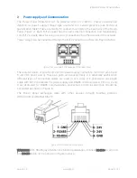
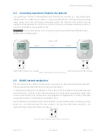
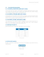
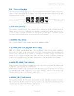
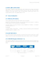
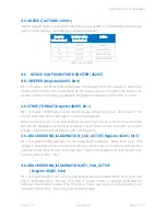
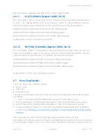
for Icon Indication.
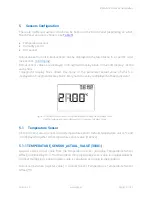
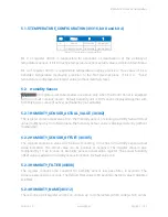
4.8.1.1 LCD_ICON_DISPLAY (40219)
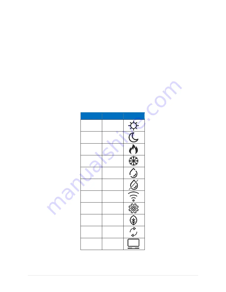
Each bit of the register is responsible for displaying a particular icon.
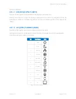
Setting true value for single bit displays appropriate icon which is assigned to that bit
according to Table no. 12 below. By default, all icons are hidden (all bits of the register are
“false”
).
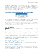
4.8.1.2 LCD_ICON_FLASHING (40220)
Each bit of the register switches on blinking of particular Icons.
Setting true value for a particular bit causes blinking of a single Icon which is assigned to
that bit according to Table no. 12 below.
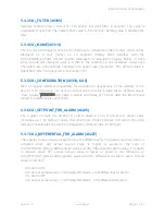
Bit
Icon Name
Icon
0
Sun
1
Moon
2
Heating
3
Cooling
4
Humidfire
5
Dehumidfire
6
Wireless
7
Settings
8
Eco
9
Recirculation
10
PC
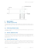
Table 12 LCD Icon Display

