iSMA-B-LP Room Panel/Modbus
version 1.3
www.gc5.pl
Page 9 / 121
2
Power supply and Communication
The Room Panel iSMA-B-LP can be powered with 24 V AC/DC. Power consumption
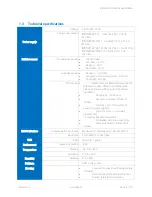
depends on power supply voltage type used and CO
2
sensor presence (see Technical
specification table). There are two RJ12 sockets mounted on the back side of the Room
Panel (Figure 2). Each RJ12 socket has the same internal connection and functionality.
Two RJ12 sockets allow for using in and out connections for other devices in the network.
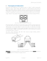
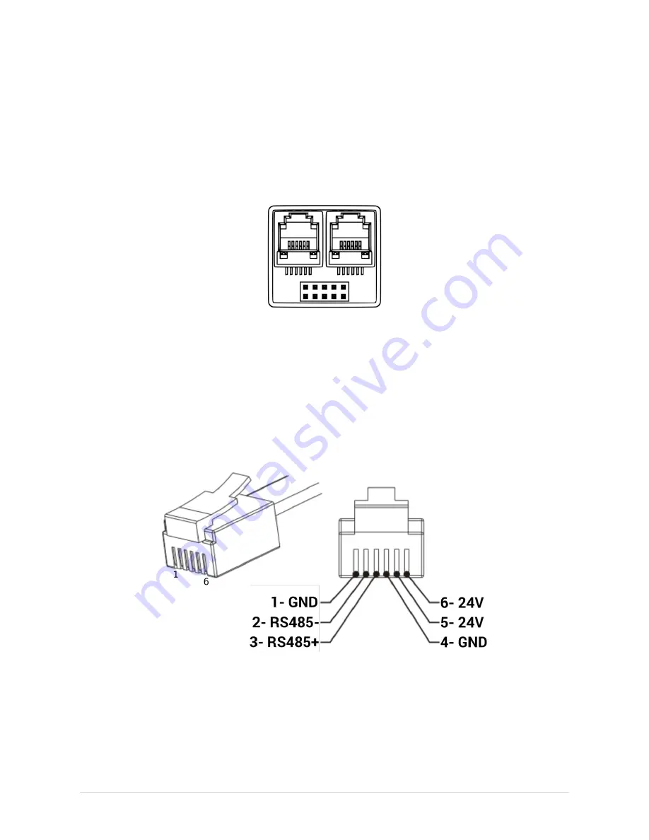
Power supply can be connected through the RJ12 connector as shown in Figure 3 below.
Figure 2 RJ12 sockets in the back side of the Room Panel
There are two pairs of pins for 24 V AC/DC power supply connection (+24 V DC pins 5 and
6, -24 V DC pins 1 and 4). These pin pairs can be used freely. It is especially useful when
different types of connection cables are used (4 or 6 core). It is possible to use single
cable with RJ12 connectors for power supply and RS485 communication. Pins no. 2 and
3 are dedicated for RS485 communication connection. Communication bus should be
connected as shown in Figure 6.
The Room Panel exchanges data with other devices through Modbus protocol
(RTU/ASCII) and BACnet MS/TP.
Figure 3 RJ12 socket pin configuration
WARNING! With RS485 pay attention to standard polarization. Connect RS485+ to pin no. 3
and RS485- to pin no. 2 as shown in Figure 3 above.


