37
ASSEMBLY AND INSTALLATION
inVENTer
®
iV14R/iV14V ventilation system
•
Installation and operating instructions
NOTE
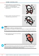
Contamination of wall sleeve and ixing elements.
Risk of damage to the cutout insulation of the thermal accumulator so no longer possible to it the
inner cover!
► Insert protective discs between the wall sleeve and masonry before illing the gap with foam.
TIP
Only remove thread locking on ixing elements once work on the wall is completed. This avoids
contaminating the thread. Stabilise the wall sleeve before illing with foam by sliding in the
thermal accumulator or suitable material to retain the shape.
►
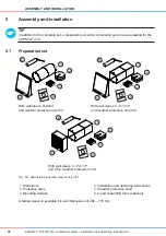
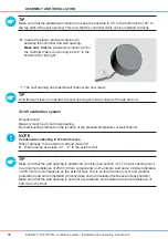
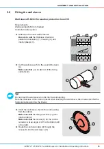
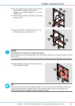
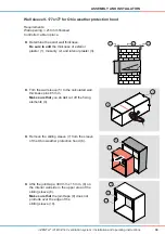
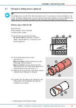
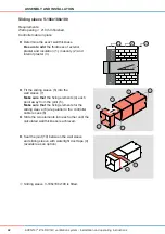
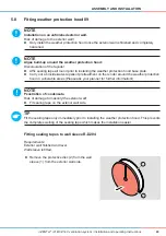
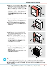
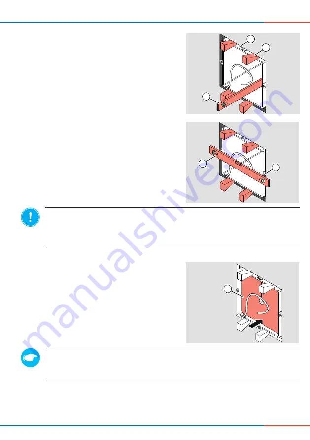
Align the position of the ixing elements (13)
horizontally using a spirit level (14).
3
1
4
1
►
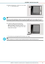
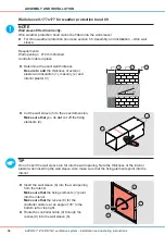
Fix the wall sleeve (10) in place on the interior
and exterior wall sides with mounting
wedges (11) to create a slope of 1 – 2° to the
exterior wall.
►
Check the slope of the wall sleeve (10) using a
spirit level (12).
0
10
1
1
1
2
1
►
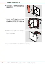
Insert protective discs (15) into the wall sleeve
from outside and inside.
5
1

