30
ASSEMBLY AND INSTALLATION
inVENTer
®
iV14R/iV14V ventilation system
•
Installation and operating instructions
TIP
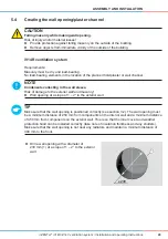
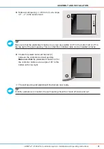
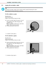
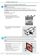
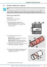
Make sure that the plaster/wall channel is as near as possible to 45° to the bottom left or 45° to
the top right of the wall opening. This is so that the controller cable can be installed correctly.
Ö
Ö
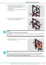
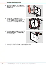
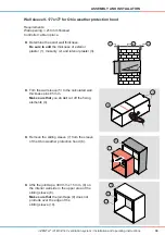
The wall opening and plaster/wall channel are now ready.
TIP
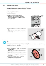
Until the wall sleeve is inserted, the wall opening should be closed off inside and out.
iV14V ventilation system
Requirements:
Masonry must be dry and load-bearing.
No load-bearing elements in the location of the planned hole/plaster or wall channel.
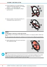
NOTE
Condensate collecting in the wall sleeve.
Risk of damage to the exterior wall and masonry!
► Wall opening at a slope of 1 – 2° to the exterior wall.
TIP
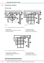
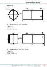
Make sure that the wall opening is positioned correctly (see section 3.2). The wall opening must
be a minimum distance of 250 mm from components on the interior wall and a minimum distance
of 450 mm from components on the exterior wall. This is so that the inner cover and weather
protection hood can be installed correctly (take note of insulation thickness and any shutters).
Make sure that the wall opening is not near any radiators and maintain a minimum distance of
300 mm to the front.
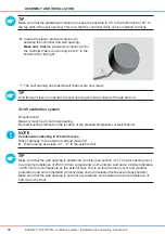
►
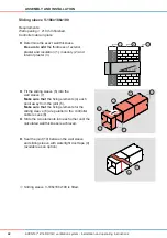
Create the plaster and wall channel (2)
between the controller and wall opening.
Make sure that
the plaster/wall channel (2) for
the controller cable is at an angle of 45° to the
bottom left or top right.
2

