25
WIRINg/ELECTRICAL CONNECTIONS
inVENTer
®
iV14R/iV14V ventilation system
•
Installation and operating instructions
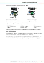
Connection for supply air mode/extract air mode
Fig. 24:
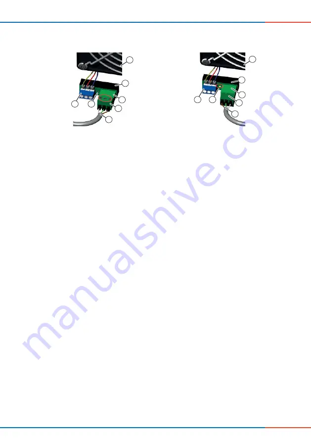
Start settings: Connector position for extract air/supply air
The running direction of the fan depends on the alignment of the connector's locking screws.
Start-up arrangement
In extract air mode, the green connector's locking screws are pointing up and visible. The LED is
not illuminated (see ig. 24: Start settings: Start direction for extract air).
In supply air mode, the green connector is rotated. The locking screws are pointing down and
are not visible. The LED illuminates (see ig. 24: Start settings: Start direction for supply air).
Start direction for extract air
Locking screws visible
Start direction for supply air
Locking screws not visible
5
1
2
3
4
7
6
5
1
3
4
7
6
2
1 Reversible fan
2 Plug connector of fan
bus 4.0
3 Socket
4 Controller connector
5 Controller cable
6 LED
7 Connection terminal
for fan

