


Chapter 4: Web configuration
NS3552-8P-2S-V2 User Manual
307
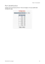
4. Set “MEP5” = Port 2, “MEP6” = Port 1, and VLAN ID = 3001. Click
Set
to save the
ERPS configuration for switch 3.
Note:
To avoid a loop, do not connect switches 1, 2, and 3 together in the ring topology
before configuring the end of ERPS.
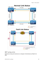
Follow the configuration or ERPS wizard to connect switch 1, 2, and 3 together to
establish ERPS application:
• MEP2
←→
MEP3 = Switch 1 / Port 2
←→
Switch 2 / Port 2
• MEP4
←→
MEP5 = Switch 2 / Port 1
←→
Switch 3 / Port 2
• MEP1
←→
MEP6 = Switch 1 / Port 1
←→
Switch 3 / Port 1
Power over Ethernet (PoE)
Providing up to 24 PoE in-line power interfaces, the industrial managed switch can
easily build a power central-controlled IP phone system, IP camera system, and Access
Point (AP) group for the enterprise. For example, 24 cameras/APs can be installed for
company surveillance demands, or to build a wireless roaming environment in the
office. Without power-socket limitation, the industrial managed switch makes the
installation of cameras or WLAN APs simple and efficient.
Summary of Contents for NS3552-8P-2S-V2
Page 1: ...NS3552 8P 2S V2 User Manual P N 1073552 EN REV B ISS 25JAN19 ...
Page 41: ...Chapter 3 Switch management NS3552 8P 2S V2 User Manual 39 ...
Page 73: ...Chapter 4 Web configuration NS3552 8P 2S V2 User Manual 71 ...
Page 147: ...Chapter 4 Web configuration NS3552 8P 2S V2 User Manual 145 ...
Page 511: ......