Design Guide
153
EMI and Mechanical Design Considerations
11.2.4
Heatsink Effects
Heatsink grounding may be an effective way to reduce system EMI emissions. Noise coupled from
the processor package to the heatsink may cause it to act as an antenna and re-radiate the noise.
Heatsink size, shape, fin pattern, orientation and material may all impact its ability to reradiate the
high frequency signals. Designers will have to experimentally investigate the behavior of a
particular heatsink to determine its EMC performance.
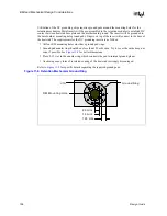
Grounding of the heatsink through the processor package is not possible with the current package
implementation, but may be an option at some time in the future. Therefore, system designers must
either design their own heatsink grounding solution, or use the heatsink grounding device
described in
When designing a grounding mechanism for the heatsink, care must be taken to minimize the
impedance and distance between the ground paths. Typical guidelines suggest ground points
should be separated by less than ¼ wavelength of the third harmonic of the processor core
frequency.
Grounding materials should be selected to eliminate galvanic action between the various metals in
contact. Oxidation of the various materials should also be considered because some oxides are non-
conductive (for example, aluminum oxide), and will degrade EMC performance over time.
Manufacturing process residue or coatings to prevent oxidation should also be checked for
conductivity, especially at high frequencies.
11.2.5
EMI Ground Frames and Faraday Cages
Grounding of heatsinks may reduce EMI, but that alone may not be sufficient to pass the required
tests. Additional shielding of the processor itself may be necessary. A Faraday cage placed around
the processor may provide a reduction in radiated noise and make chassis design easier.
A true Faraday cage would completely surround the source of radiation and contain all radiated
energy. Within the limitations of processor packaging and motherboard assembly, it is not possible
to create a true Faraday cage around the processor. By using the heatsink and motherboard ground
plane as two sides of the cage and a metal frame to enclose the remaining four sides, a reasonable
approximation of a Faraday cage can be achieved.
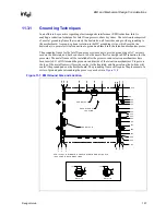
Intel has designed a “picture frame” type of grounding device, called an EMI ground frame, that
fits between the processor and heatsink (see
). With this implementation, it is
unnecessary to design a separate heatsink grounding mechanism because the frame will provide
this capability. OEMs who choose to use the Intel designed grounding frame will need to provide
ground pads on the top layer of the motherboard around the processor socket. These pads will
provide the necessary ground continuity to complete the Faraday cage. Exact physical dimensions
of the frame and the material used are provided in the processor IGES and Pro-E models for
enabled components. The required motherboard ground pad descriptions are provided in
Summary of Contents for Xeon
Page 24: ...Introduction 24 Design Guide This page is intentionally left blank ...
Page 30: ...Component Quadrant Layout 30 Design Guide This page is intentionally left blank ...
Page 52: ...Platform Clock Routing Guidelines 52 Design Guide This page is intentionally left blank ...
Page 66: ...System Bus Routing Guidelines 66 Design Guide This page is intentionally left blank ...
Page 118: ...Intel 82870P2 P64H2 118 Design Guide This page is intentionally left blank ...
Page 146: ...I O Controller Hub 146 Design Guide This page is intentionally left blank ...
Page 148: ...Debug Port 148 Design Guide This page is intentionally left blank ...
Page 210: ...Schematic Checklist 210 Design Guide This page is intentionally left blank ...
Page 220: ...Layout Checklist 220 Design Guide This page is intentionally left blank ...
Page 222: ...Schematics 222 Design Guide This page is intentionally left blank ...


